News:


  • April 27, 2024, 01:21:28 PM

Login with username, password and session length

Author Topic: Side area distribution  (Read 1767 times)

Offline Curare

  • 2014 Supporters
  • Trade Count: (0)
  • Captain
  • *
  • Posts: 779
Side area distribution
« on: June 19, 2023, 03:10:44 AM »
Hey guys, just another off-the-cuff question, hopefully this one should be reasonably straightforward, although in stunt circles it seems nothing ever is.

I've been toying around with a new ship design, and it seems that a lot of (not all)stunt ships seem to have a lot more side area behind the CG rather than forward of it.

I was under the impression that having more area aft of the CG would make the aircraft weathervane, and sort of "tip in" to overhead maneuvres.

Am I wrong? If so why?

Is there a decent starting point for side area in terms of percentage? My current design area centroid is about 55% of the fuselage length.

Greg Kowalski
AUS 36694

Offline john e. holliday

  • 24 supporter
  • Trade Count: (0)
  • Admiral
  • *
  • Posts: 22773
Re: Side area distribution
« Reply #1 on: June 19, 2023, 12:10:50 PM »
I beleive there is a balance on side area behind the CG.  I have built several of Dave Tribles designs and if you look at the Nobler there is more side area behind the CG.  I think the reason is so the plane stays out on up wind side of circle and doesn't pull so hatd on down wind side.  My thoughts. D>K
John E. "DOC" Holliday
10421 West 56th Terrace
Shawnee, KANSAS  66203
AMA 23530  Have fun as I have and I am still breaking a record.

Offline Dave Hull

  • 24 supporter
  • Trade Count: (0)
  • Admiral
  • *
  • Posts: 1908
Re: Side area distribution
« Reply #2 on: June 19, 2023, 05:13:14 PM »
Hmmm. Ok, let me try a few thoughts in a few sentences..... (Hah!)

Doc's onto it. What you want is aerodynamic balance that is unique to a stunt plane--which is different from a full-size plane. Because it is tethered to the ground and on each trip around the circle it sees lateral winds in both directions you would like the design to aid the pilot with stable flight and not have the side area fight the pilot with loss of line tension upwind.


--Design the airframe to minimize loss of line tension flying straight and level in high winds on the upwind side

--Fins are used to stabilize things. Think of the fletching on an arrow and the fixed fins on an unguided rocket. The lateral area needs to be aft-biased.

--If there was no wind or drift then the center of lateral area would matter much less to us. On a combat plane there is very little lateral area. They generate line tension via airspeed (radial acceleration). The slower you want to go, the better your aero balancing needs to be to keep the handle forces within a limited range.

--Trying to generate lots of line tension overhead by yawing the whole fuselage is probably not optimal. I suppose the more horsepower you have to spend, the more viable this gets, but it seems like it would cause lots of other trim issues in places you care about.

--The higher the wind (and the lighter the plane) you plan to fly, the more "right" you need to get this.

--Always think of the plane as rotating in 3-space around its CG. Calculate areas ahead of the CG and behind. What is a good ratio? I don't know. I would look at a plane with similar trim techniques: with or without rudder offset; with or without engine offset; forward or aft CG; etc. [more goes here]  But don't cherry pick one feature from one plane and scab it onto a new design without considering all of the related features that contribute to yaw position and stability. Or else make everything adjustable and go "in search of...."

--Mathematically, sum the lateral moments due to side loading (body drag) fore and aft about the CG to see where neutral is.

--It isn't just projected lateral area, although that is a good start. The cross-sectional shape matters, too. I suspect that it is a fairly small effect until the wind speed becomes a significant percentage of the airspeed.

Online Ken Culbertson

  • 24 supporter
  • Trade Count: (0)
  • Admiral
  • *
  • Posts: 6126
Re: Side area distribution
« Reply #3 on: June 19, 2023, 05:47:24 PM »
Let me add twin tails to the discussion.  What is the actual side area of a twin?  One rudder or both?  I don't know but I can attest that they fly very well in the wind unless you miss the wind in a maneuver.  Then not so much.   Excellent balancing of line tension and great overhead which is what high aft area is supposed to provide.

Ken
AMA 15382
If it is not broke you are not trying hard enough.
USAF 1968-1974 TAC

Offline Air Ministry .

  • Trade Count: (0)
  • Admiral
  • ******
  • Posts: 4986
Re: Side area distribution
« Reply #4 on: June 20, 2023, 08:56:18 PM »
Cording to the Aero Nauticists  %^@ 
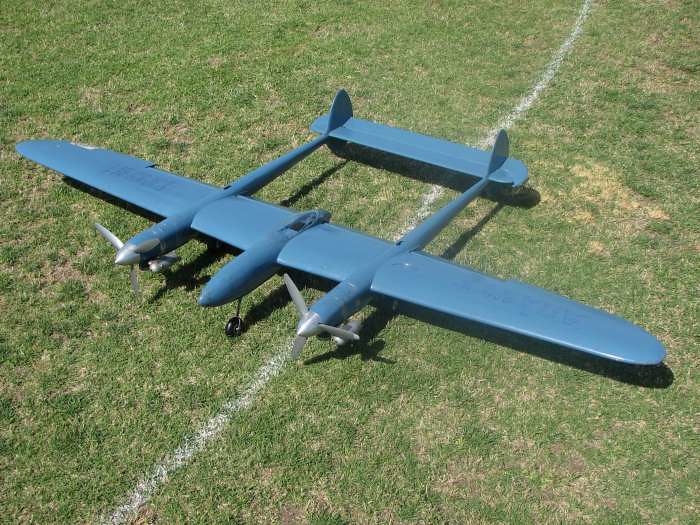
The TWIN Tails ( from studying for the P #* , or is that P-38 , Have Side Gust Responce of a single tail & dirctional stabilty  of the two , as its got DOUBLE the projected side view area .
I found the yaw stabilty of this thing very good to excellent , at the ' test ' stage , which was something like wot'd be the ragged edge , with only two old OS 35-S's . It'd even do wingovers & the lower rounds on the OUTER , with a bit of leaning on the handle and a bit of a slow dive to assist . As in Go over & inverted and back , on the outer . With the 10x4s on it . 9x6s were useless .

SIDE AREA .  >:(

My blue spitfire with the invasion stripes , did the shedule on the 2nd or third flight , or both , with a weak ST 60 , and flew well .
From then on it was a [pig .. Yawinging , rocking , snaking , bobbling and kniveing . With a G 51 TOO , so I put the A ST 60 backin .

One Day I whittled the spare cowl ( the Deeper P.R. version , goes up ( or Down  ;D ) to the Head ! . LIKE IT WAS AT FIRST !
the Std ish cowls curved from the spinner back - AND has a big ugly eggish opening ( like windy's )

Thus : Fwd Side Area - effecive  -  Massive trim Change . Mutter Fume . Particularly with C G near aft limit .

Whammo , back to well behaved .  %^@    ???    :-\  Tho it did rock and skid htting its slipstream the other day . i should be doping
the replaced outer covering over the Std &age ribs in the wing ends , like wot It shoulda Had , straight off rather than the THINNED ONES .
we'll see ! .

P R type Cowl , pitcher .


NOW , cording to our friend Windy , or is that Jose ; Big Jim Favoured deep noses ( on Aeroplanes ) to balance theside area , in the overheads & wingovers ,
as the air sitting on the inner nose , holds it up . So stops it falling in .

Further , a rounded tapered un plank fuse. would slightly weave & yaw ( both lateral ) flying to slow on the near stall ecge ( Plank wing spit. ) .
As it ' Hit the Cam ' , you felt the Aerodynamic Surfaces ( 1/4 Hard New Gunea Balsa Sheet ) ' Kick In ' and GROOVE it , both laterally & in the vertical .
As if you had NO Fuselage , it was ! .

So , There you go . You did ask ! .

This Thing DOSNT really have ANY side area , in a sense . Its ALL ROUNDED . As what someone was talking off somewhere , regarding WIND . ( Ref: P-38 Comments )

Ref ' Twin Tail Q ' . its gottem .

A NOTHER ASPECT of the LONG WING ( wot wasnt asked for ) is the Leadout Guide way out there , it seems way more conspicuous , shall we say . or definative . or THERE !
thats 2 metre / 78 inch . Too Big . ( redrawn 7/8th to or something to LESS and 580 Sq in , from 680 for two FSR 25s  :P )The 6 foot / 72 Inch Mew Gull exhibited that factor also .
The CONCERN is the Tip weight , too - has a L  O  N  G   moment , out there . So I dont put it there !  ;D

And YEA , The Phantom weathervanes with to big flying surface - FIN  , as against a similar but lower / smaller less outrageous one .. Bob Hunt took a dislike to fins , with His Genisis  S?P .

Perhaps VERTICAL FLYING SURFACE  ( fin / rudder ) are a seperate if pertanant factor . The ' Big Jim '  class, seems to minimalise that . Re: previous FUSE AREA B. J. Info . :P

So , Theres Fuse side Area , AND Flying Surface - Vertical .  It would seem .
« Last Edit: June 20, 2023, 09:14:07 PM by Air Ministry . »

Offline Tim Wescott

  • 2016 supporter
  • Trade Count: (0)
  • Admiral
  • *
  • Posts: 12808
Re: Side area distribution
« Reply #5 on: June 21, 2023, 08:35:27 AM »
I built my own-design semi-scale Cessna Airmaster stunt trainer.  I messed up the scaling of the fin, and ended up with a plane that had a wicked oscillation any time it was upset -- as, for instance, square maneuvers, or hitting turbulence.  It'd come out of the wingover and take half a circle to settle down.

I looked at an Impact side profile, scratched out some numbers on a sheet of paper, and made the tail bigger to match.  The plane settled down and -- very surprisingly for a high wing plane -- flew pretty good without the nastiness.
AMA 64232

The problem with electric is that once you get the smoke generator and sound system installed, the plane is too heavy.

Offline Tim Wescott

  • 2016 supporter
  • Trade Count: (0)
  • Admiral
  • *
  • Posts: 12808
Re: Side area distribution
« Reply #6 on: June 21, 2023, 08:58:47 AM »
For that matter, the Genesis flies fine with its "no tail", but if you look at that tall rear fuselage with it's long skinny fin and run the numbers -- it's pretty close to an Impact.
AMA 64232

The problem with electric is that once you get the smoke generator and sound system installed, the plane is too heavy.

Offline Curare

  • 2014 Supporters
  • Trade Count: (0)
  • Captain
  • *
  • Posts: 779
Re: Side area distribution
« Reply #7 on: June 21, 2023, 07:22:26 PM »
Tim, I*think* I understand the design philosophy of the Genesis (perhaps Bob might confirm or deny this), low aspect ratio fins are more suited to stunt, if I recall Bill Netzband studied this in depth, and most of his designs have long low fins,.

If you have enough side area at the aft end of the fuselage, one could assume the fin could be completely omitted.

Interesting obvervation with the the Airmaster. I wonder if it needed more fin area because the fin was getting blanketed by the wing?  I've seen similar issues with RC aircraft where we needed to increase the fine height to get out of the wash of the wing in high AoA maneuvres.

Greg Kowalski
AUS 36694

Offline Tim Wescott

  • 2016 supporter
  • Trade Count: (0)
  • Admiral
  • *
  • Posts: 12808
Re: Side area distribution
« Reply #8 on: June 21, 2023, 09:56:29 PM »
Interesting obvervation with the the Airmaster. I wonder if it needed more fin area because the fin was getting blanketed by the wing?  I've seen similar issues with RC aircraft where we needed to increase the fine height to get out of the wash of the wing in high AoA maneuvres.

Nah.  It needed more fin because when I scaled everything around to make a stuntish Airmaster I screwed up the calculation of the fin area by a factor of two.  It was a simple math error, and not being awake enough to my mistake to see that the thing was teeny.

It was utterly, entirely, my mistake.  Fortunately I learned from it.
AMA 64232

The problem with electric is that once you get the smoke generator and sound system installed, the plane is too heavy.

Online Dave_Trible

  • 24 supporter
  • Trade Count: (0)
  • Admiral
  • *
  • Posts: 6153
Re: Side area distribution
« Reply #9 on: June 22, 2023, 04:06:19 PM »
I like to keep at least 25% of the total fuselage side area forward of the CG.  To me the most critical area in the pattern in this respect are the vertical maneuvers,  especially ABOVE 45 degrees.   On some off our larger ships this area can be up to 200 sq. in.- enough to fly the airplane on in knife edge flight.   In the wind as you climb above 45 the fuse can really weathervane toward you when tension is already light and can blow you out of the maneuver or at least reduce line tension to the point you can't get enough pull to hold adequate control deflection thereby opening the maneuver up unintentionally .  Bigger engines or more speed can overcome this fairly well these days but if you look at earlier designs that flew best in the wind, mostly the I beam Detroit style (think Ares) ship very often were hard to beat.  Those profiles were deeper nosed,  smaller rear fuse and rudder designs which could fly on the diminutive Fox and gain some lift from the forward side area or at least not have to fight a high lift factor from the rear end.  You can look at that billboard rear end of the Nobler and wonder but look at how much area is FORWARD of the CG...........


Dave
AMA 20934
FAA Certificate FA3ATY4T94

Online Brett Buck

  • Trade Count: (0)
  • Admiral
  • ******
  • Posts: 13741
Re: Side area distribution
« Reply #10 on: June 23, 2023, 12:21:40 AM »
Hey guys, just another off-the-cuff question, hopefully this one should be reasonably straightforward, although in stunt circles it seems nothing ever is.

I've been toying around with a new ship design, and it seems that a lot of (not all)stunt ships seem to have a lot more side area behind the CG rather than forward of it.

I was under the impression that having more area aft of the CG would make the aircraft weathervane, and sort of "tip in" to overhead maneuvres.

Am I wrong? If so why?

Is there a decent starting point for side area in terms of percentage? My current design area centroid is about 55% of the fuselage length.

   My buddy Ted Fancher called my airplane "3 billboards flying in formation", so I am rather noted for lots of side area.

   It does tend to make it weathervane on the upwind side of the circle, but I do not consider that an advantage, because it makes it more difficult to turn up into the wingover and square 8 cleanly.

  I am not concerned with overhead or vertical line tension, that's why I have a piped 40 or piped 61. My goal was pretty simplistic, to make it table enough in yaw to handle lots of power without generating excessive yaw. It's for passive yaw stability, pretty simple, arrows flight straight because they have fins, I made my fins bigger. The mix of side area and fin/rudder is as big as I can make it without being poorly-shaped or any uglier than it has to be. It comes pretty naturally, because I have a very thick wing and have enough fuselage below it to pass the pipe through from the front. You more-or-less need to keep the fuselage deep all the way to the back, or it ends up having the "pregnant guppy" look.

     Earlier attempts by myself and others to improve whip-up (in the dismal days of 4-2 break engines) had us making the fuselage as small as possible to avoid "kiting" in the wind. That was a comprehensive misunderstanding of the dynamics, which have absolutely nothing to do with the side area, but with induced drag, and using crap engines of the day - and not enough piloting skill, trimming skill,  and engine setup knowledge to handle it properly.  This was all back in the early-mid 80s, so, it didn't take that long to figure out the mistake, then the issue was power handling/yaw stability.

    Similarly, there was a school of thought about fuselage lift and treating overhead tension as if it was "knife-edge" flight like RC and full-scale. That is also irrelevant, centrifugal force is sufficient and trying to lift from the fuselage also requires large yaw angles, which makes it difficult all the rest of the time. The airplanes designed to fly at large yaw angles (like the Firecracker) need small fuselages, not large ones, to reduce the roll/yaw coupling.

   Both problems are more-or-less moot, whipping up is a dead issue, you don't need large props to get good performance, so the power handling is also not a problem.

     Brett

Online Igor Burger

  • Trade Count: (0)
  • Admiral
  • ******
  • Posts: 2166
Re: Side area distribution
« Reply #11 on: June 23, 2023, 12:48:36 AM »
Hey guys, just another off-the-cuff question, hopefully this one should be reasonably straightforward, although in stunt circles it seems nothing ever is.

I've been toying around with a new ship design, and it seems that a lot of (not all)stunt ships seem to have a lot more side area behind the CG rather than forward of it.

I was under the impression that having more area aft of the CG would make the aircraft weathervane, and sort of "tip in" to overhead maneuvres.

Am I wrong? If so why?

Is there a decent starting point for side area in terms of percentage? My current design area centroid is about 55% of the fuselage length.

No, you are not wrong, but it will happen only if model really moves down from top of sphere. And it does not happen while you have tight lines.

There was already something written about it in the past. I will collect it briefly, but let me to write 2 notes before:

1/ the point of question is not "length" distribution but rather area multiplied by distance. Means something like moment area.
2/ the balance point is not at 50% as it is aerodynamic surface (the side of fuselage is a wing with extremely small aspect ratio), it is rather 25%, but that percentage can change as function of yaw angle.

So ... we have 3 cases:
larger tail - such model has good yaw stabilization, good resistance to gyroscopic forces etc, but it will yaw with side wind and that means wind will put it out of the trim in wind and turbulence, because it will fly yawed and thus LO position will be off the optimal place

larger nose - this configuration is used on indoor models where we do not have enough centrifugal forces to keep tight lines. Model gets line tension from 20degrees or more of yaw (fuselage has almost the same area as the wing) and if model slows down overhead, that large nose will turn nose out of the circle to give enough line tension for safe maneuvering, I think everyone who tried our GB indoor models will know the effect. This works because line tension cancels aerodynamic forces (from imbalance of large nose) yawing model out.

balance point - that is case of my MaxBee, I tried to find balance point on profile model of fuselage in wind and the real model has only small reserve of stability. That works very well in in wind, turbulence, it will also fly well on upwind side of circle (happens on contests), but it definitely needs artiffical stabilization of precession by Rabe rudder and also properly set combination of leadouts, rudder and motor offset.

Online Bob Hunt

  • 23 supporter
  • Trade Count: (0)
  • Admiral
  • *
  • Posts: 2705
Re: Side area distribution
« Reply #12 on: June 23, 2023, 07:16:31 AM »
I’ve thought a lot about side area distribution over the years and have had a lot of success with my models by doing what I’m going to impart now.

A lot of this will seem like I’m stating the obvious… and I am! But we need to establish a common starting point. Our models are a lot like weathervanes when they are down wind - which is where we do most of our maneuvers - with the balance point being very far forward of the vertical fin. The typical largish vertical fin is “pushed” outward, and the model tends to “pivot” to a degree at the balance point, turning the nose inward. That’s the obvious part...

Because there is typically more vertical fin area above the vertical center of gravity of the model, there also tends to be a rolling component thrown in. The wind tries to roll the model to the right when downwind. So, we have a coupled left yaw and right roll situation. Obviously (again) this whole scenario is reversed when we are upwind. There we have a right yaw, left roll thing going on.

Many years ago I designed a model called Genesis (you may have heard of it…). And, I cannot take any credit for thinking about side area distribution at that time in my life (when not thinking about Stunt, I was thinking about girls, motorcycles, and cars… Fortunately in that order).  All of the Genesis models flew very well in wind, with little to no weather vane effect. The thought that I’d discovered something important didn’t dawn on me until I started building models once again with vertical fins. I had taken a nearly decade long sabbatical into RC Pattern flying, and there a rudder was absolutely necessary…

I had designed an RC Pattern ship called Crossfire. It was so named because I brought some CL thinking to that design, and the name reflected the crossfire of technology between RC and CL. When I had my fill of RC (I missed the pull of the lines. I considered having someone stand in front of me while I was flying RC and try to pull the transmitter out of my hand; not one of my more cogent thoughts). Anyway, when I returned to CL I decided to build a CL version of the Crossfire having learned that rudders were not necessarily bad things. That’s when I became very aware of side area distribution. I typically fly off of grass fields, and there wheel pants are not the hot ticket. I made a set of simple flat spats to go on the “grass gear” and proceeded to fly. The model was okay in good air, but it was a bear to fly in wind; it did all sorts of ugly things. But, when flown with the rather largish wheel pants in the wind, it was a delight. I reasoned that the wheel pants being forward and below the vertical CG balanced the effect of the vertical fin being up and aft of the vertical CG, and the results was a model that didn’t yaw or roll downwind. This was proved once again with my Saturn design, which also has a largish vertical fin. I did add a bit of a ventral fin to that model to try and even out the vertical side area aft, but even then with the grass gear and smallish spats fitted, the model had a lot of left yaw and right roll tendencies in wind. That model was fitted with very large wheel pants for pavement operations and - just like with the Crossfire - that cured the yaw and roll problems. It was a great wind airplane with the wheel pants installed. I took a bit of ribbing about those pants from my fellow competitors… until they had to compete against that ship in contests. It was a very successful design for me.

I tend to gravitate towards jet-style ships of late, and design them with fairly large, painted on canopies. I also fit them with the large wheel pants, and the result is even better high wind performance downwind. Forward side area is a good thing!

Offline Dennis Toth

  • 2020 supporter
  • Trade Count: (0)
  • Admiral
  • *
  • Posts: 4228
Re: Side area distribution
« Reply #13 on: June 25, 2023, 08:18:44 AM »
Bob makes an interesting point. Adding the wheel pants adds frontal area below the vertical CG balancing the roll and yaw force. If you think about this a bit it seems if you use some rudder offset it would also counteract the yaw down wind and if the rudder is on the normal top position counter some of the vertical CG roll. Geez those guys back in the day may have knew what they were doing after all.

Seems a trim-able rudder might be a feature worth looking into. Even a modified Rabe rudder that would allow not only how much it moves but also how much it moves with both up and down elevator movement would be interesting trim feature. The current trend is everything is straight, we overcome these downwind forces with sheer power. Maybe with some of the old trim features with todays power one could fly slower in challenging conditions that always seem to come in second round.

This would be easiest to test on a current day profile ship where you can have easy access to engine and rudder to try and see what works. I recently had a Ringmaster that had issues up top, I read the Guided Whistle article by Walt Huges in which he indicated that ships having trouble doing good vertical 8's need more engine offset. I tried it and it does improve the line tension up top significantly. Will next add a small tab to the rudder (no offset now) to see if that helps calm down the very slight hunt in level flight as the wind comes up (seems the weathervane could cause the ship to yaw in-out around the lines causing the slight hunt).

Good information Bob, lots of food for thought.

Best,    DennisT

Offline Curare

  • 2014 Supporters
  • Trade Count: (0)
  • Captain
  • *
  • Posts: 779
Re: Side area distribution
« Reply #14 on: June 25, 2023, 06:42:35 PM »
I’ve thought a lot about side area distribution over the years and have had a lot of success with my models by doing what I’m going to impart now.

A lot of this will seem like I’m stating the obvious… and I am! But we need to establish a common starting point. Our models are a lot like weathervanes when they are down wind - which is where we do most of our maneuvers - with the balance point being very far forward of the vertical fin. The typical largish vertical fin is “pushed” outward, and the model tends to “pivot” to a degree at the balance point, turning the nose inward. That’s the obvious part...

Because there is typically more vertical fin area above the vertical center of gravity of the model, there also tends to be a rolling component thrown in. The wind tries to roll the model to the right when downwind. So, we have a coupled left yaw and right roll situation. Obviously (again) this whole scenario is reversed when we are upwind. There we have a right yaw, left roll thing going on.

Many years ago I designed a model called Genesis (you may have heard of it…). And, I cannot take any credit for thinking about side area distribution at that time in my life (when not thinking about Stunt, I was thinking about girls, motorcycles, and cars… Fortunately in that order).  All of the Genesis models flew very well in wind, with little to no weather vane effect. The thought that I’d discovered something important didn’t dawn on me until I started building models once again with vertical fins. I had taken a nearly decade long sabbatical into RC Pattern flying, and there a rudder was absolutely necessary…

I had designed an RC Pattern ship called Crossfire. It was so named because I brought some CL thinking to that design, and the name reflected the crossfire of technology between RC and CL. When I had my fill of RC (I missed the pull of the lines. I considered having someone stand in front of me while I was flying RC and try to pull the transmitter out of my hand; not one of my more cogent thoughts). Anyway, when I returned to CL I decided to build a CL version of the Crossfire having learned that rudders were not necessarily bad things. That’s when I became very aware of side area distribution. I typically fly off of grass fields, and there wheel pants are not the hot ticket. I made a set of simple flat spats to go on the “grass gear” and proceeded to fly. The model was okay in good air, but it was a bear to fly in wind; it did all sorts of ugly things. But, when flown with the rather largish wheel pants in the wind, it was a delight. I reasoned that the wheel pants being forward and below the vertical CG balanced the effect of the vertical fin being up and aft of the vertical CG, and the results was a model that didn’t yaw or roll downwind. This was proved once again with my Saturn design, which also has a largish vertical fin. I did add a bit of a ventral fin to that model to try and even out the vertical side area aft, but even then with the grass gear and smallish spats fitted, the model had a lot of left yaw and right roll tendencies in wind. That model was fitted with very large wheel pants for pavement operations and - just like with the Crossfire - that cured the yaw and roll problems. It was a great wind airplane with the wheel pants installed. I took a bit of ribbing about those pants from my fellow competitors… until they had to compete against that ship in contests. It was a very successful design for me.

I tend to gravitate towards jet-style ships of late, and design them with fairly large, painted on canopies. I also fit them with the large wheel pants, and the result is even better high wind performance downwind. Forward side area is a good thing!

Bob, you got me thinking (always a dangerous thing), and so I plotted the centre of area of the Crossfire fuselage, and then a second plot of the fuselage AND pants, and loe and behold the centre of area (centroid) moves further forward and almost on centreline! I would hazard a guess and say that if I could plot two landing gear legs it would get even better! (the CG marks determine the centroid)

Further to this, it does show that the large forward canopy is doing a lot to bring that centroid forward, even with what could be considered a large-ish tail for a stunter.

Greg Kowalski
AUS 36694

Offline Curare

  • 2014 Supporters
  • Trade Count: (0)
  • Captain
  • *
  • Posts: 779
Re: Side area distribution
« Reply #15 on: June 25, 2023, 07:43:12 PM »
Further to that, the calcuated side area is around 257sq in, so that should equate to a "wing" loading of around 35oz/sq ft!
Greg Kowalski
AUS 36694

Online Ken Culbertson

  • 24 supporter
  • Trade Count: (0)
  • Admiral
  • *
  • Posts: 6126
Re: Side area distribution
« Reply #16 on: June 25, 2023, 09:08:12 PM »
Seems a trim-able rudder might be a feature worth looking into. Even a modified Rabe rudder that would allow not only how much it moves but also how much it moves with both up and down elevator movement would be interesting trim feature.


Dennis, you have just described Keith's Cam Rudder.

Ken
AMA 15382
If it is not broke you are not trying hard enough.
USAF 1968-1974 TAC

Online Bob Hunt

  • 23 supporter
  • Trade Count: (0)
  • Admiral
  • *
  • Posts: 2705
Re: Side area distribution
« Reply #17 on: June 26, 2023, 03:38:59 AM »
Bob, you got me thinking (always a dangerous thing), and so I plotted the centre of area of the Crossfire fuselage, and then a second plot of the fuselage AND pants, and loe and behold the centre of area (centroid) moves further forward and almost on centreline! I would hazard a guess and say that if I could plot two landing gear legs it would get even better! (the CG marks determine the centroid)

Further to this, it does show that the large forward canopy is doing a lot to bring that centroid forward, even with what could be considered a large-ish tail for a stunter.

Whoosh! Talk about SWAG! (Scientific Wild A** Guess) Had no idea that it was that dramatic, Greg. Thanks for doing the math. The Crossfire XLTC had tricycle landing gear and simulated front gear doors that added even more area down and forward, but I suppose the lack of wheel pants on that one didn't change the equation too much. It was a great wind flyer, however, and in a very weak moment I sold that ship. One of my big regrets...

My new twins are also very good in the wind; perhaps the extra side area of the nacelles contribute also.

Later - Bob


Online Brett Buck

  • Trade Count: (0)
  • Admiral
  • ******
  • Posts: 13741
Re: Side area distribution
« Reply #18 on: June 26, 2023, 08:42:39 AM »
Seems a trim-able rudder might be a feature worth looking into. Even a modified Rabe rudder that would allow not only how much it moves but also how much it moves with both up and down elevator movement would be interesting trim feature.


    Both Al's original mechanism, and Keiths cam system, allow this, some his his later plans showed it in with fixed differential. It moves a little bit outboard on insides and a lot outboard on outsides. You adjust it by moving the pivot points fore/aft relative to the hinge line.

   The way Al adjusted it did not just compensate for precession, because that would require the rudder to move equally in either direction, outboard on insides, and inboard on outsides. The suggested method effectively maximized line tension, which is not what you get when you compensate for precession, which makes the line tension more constant, not necessarily  more pull.


Quote
The current trend is everything is straight, we overcome these downwind forces with sheer power.

   ??

     What "downwind forces" are you suggesting be overcome? Do you mean hook them up backwards, to reduce the line tension downwind (since excessive line tension is generally the problem).

     Brett


Advertise Here
Tags:


Advertise Here