Vortex Generators & Aerobatics.
P.J Rowland.
I wrote this article for those whom wish to trial something different. A Micro Vortex GeneratorCreates a tiny vortex in the airstream over an airfoil. This vortex energizes the normally stagnant boundary layer of air on the wing's surface. An energized boundary layer is more resistant to flow separation than a stagnant boundary layer. The result is that airflow "sticks" to the wing better, permitting flight at lower airspeeds with improved control authority. Vortex generators delay flow separation and aerodynamic stalling, thereby improving the effectiveness of wings and control surfaces.
Installing 1 pair of VG's top and bottom Inboard and outboard is so easy - its a more effective way to improve the boundary layer compared with traditional techniques such as Wire along the leading edge or highpoint. It works - there is no guess work involved. Run them 20 degree's to the airflow, in a Pigeon toe configuration or.. You can also run them inboards facing 1 direction and outboard facing the opposite direction at the highpoint. I found more than 1 pair isnt anymore effective, on the stab isnt effective at all ( or that I could detect ) I have flow back to back flights with them on and off with measurable tangible results.
Try this experiment, take a glass of water and agitate the water with your hand and time how long it takes for the water to settle. Now circle your finger around like a little whirlpool and measure how long it takes to settle back down... You will find its substantially longer. Im sure there is a scientific equation for this phenomenon however its not important for this article.
Agitated water takes between 6 - 10 seconds to settle
Circled whirlpool water takes 15 - 23 seconds to settle.
You are giving the boundary layer a lot more energy to work with compared to normal turbulent airflow of a piece of wire. VG's force the airflow to move down the wing in a spiral fashion, because of the inherent nature of a Vortex form, it lasts longer, moves further down the wing and allows for less flow separation than almost any other single form of boundary layer separation.
I will admit, I dont work in the aerospace industry - however I have been experimenting with Vortex Generators of this style and reading as much as I can on the subject since 1996. I have also had several discussions with a company whom specialize in the design and application of this technology. Thats 15 years of development, I think it counts for something when you consider how many separate aircraft I've flown them on in countless configurations.
Back in 1996 my initial contacts were made with a company which still exists today - Micro Aerodynamics Inc, whom specialize in the application, design and fit out of this technology. After reading on their website about the technology the following line was a light bulb moment:
They control airflow over the upper surface of the wing by creating vortices that energize the boundary layer. This results in improved performance and control authority at low airspeeds and high angles of attack 
Photo google.com
That was enough for me to start to experiment with the idea I proceeded to make email conversations with them and discuss theory and application for the use in model aircraft, they were indeed very informative and happy to answer any questions I had at the time. As for design I havent altered the shape too much from their initial plans; the biggest most difficult factor was size.
We used the following basic principles: A Piper Meridian has a wingspan of 575 Inches or approx 43 feet. A normal size stunt plane is also 57 Inch wingspan or there about. A full sized plane Vortex generator measures 1 Long (x) .25 tall. Using the same scale my Vortex generators would need to 3/32 tall x just over 1/64 tall... obviously this was not going to be practical. This has been something that we all struggled with initially, how big do we make them? My initial tests were rather crude compared to the methods I use today. Originally I made them out of thin ply, and they were roughly ½ Inch long. We made a lot of them initially we put them all span wise, 10 % forward of the leading edge like MircoAero suggested. The distance apart was roughly 3 apart in a pigeon toe configuration and we had approximately 18 on each wing 72 in total top and bottom inboard and outboard. (This was new ground for everyone an aerobatic model aircraft, flying in a circle, with huge power to weight ratio I often asked if there was a way to calculate a more efficient place to locate them and no one knew, the consensus was to experiment.
The very first flight gave enough improvement to satisfy me that this was a technology worth pursuing. I will admit the performance of my planes at the time was average, I was only 17 years old and we were all learning the ropes about weights and aircraft design.
What benefits I saw from that initial flight remain today It didnt improve the sharpness of the corner however it was more stable and more repeatable. I felt I could bang the corner as hard as I liked without fear of having it slide down or slide out from the initial tracking location. Flying in wind proved a little easier in that I didnt experience as much drop or rise when flying upwind or downwind. Turbulence was reduced and as a result I always felt more confident flying when conditions were not perfect. The only time it didnt have any effect was flying in DEAD calm conditions where you would hit your own wake turbulence, this is still an issue with rocking around however we do not experience any dead spots or dead patches of air were the model all of a sudden looses height. We suspect this is due to there still being enough airflow moving over the wing due to the vortex created, an easier way to think about how this occurs is to visual a bird not moving forward when flying into the wind, it still has enough airflow moving over the wings to remain airborne. I have never lost a model or even come close due to this phenomenon. This is after 15 years of high level competition flying at Nationals, US Nats and World championships. Also in conditions were other fliers have lost models due to these circumstances.
With that initial model success we went on to build a new model in 1997 called Vortex this model was designed to be light, all my own numbers 52 Oz Moki .51 power and a flat stab modeled on the Impact however with a swept back hingline.
This model formed the basis for most of my experiments in Vortex generator locations and positions. It was a solid performing model and landed me my first major competition victory.
A short transcript from the article from the contest:
The winning Vortex recorded a clear victory to take the prestigious 35 year old Stunt masters Trophy PJs first big scalp. The Moki 51 powered plane, which has been impressive ever since being finished earlier this year, flew very well throughout the day and finished with a clear margin.
The Vortex has many interesting features with the line-up including: the sparless wing is heavily double tapered, the leading edge has vortex generators top and bottom for the full span, and the flaps incorporate experimental angle countering "flapettes". Total weight is 52 ounces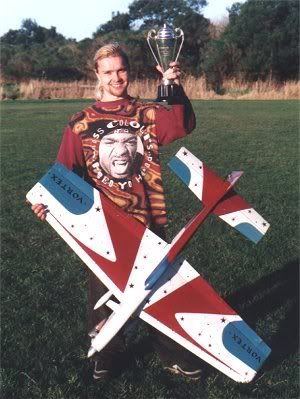
The model ended up with 6 pairs (6/48 configuration or 48 VGs in total ) top and bottom, down from the initial 8/72 configuration. The size also reduced slightly but was still larger than I use today handling and installation was always an issue.
This came about most from my frustration at knocking them off, and that I was sick of making so many. I found out from the early flights that even when several were knocked off due to handling the performance remained. We then continued over time reducing them. The 1997 Vortex took the most of the experimenting, it was very easy down at the field, - a bottle of CA and some tweezers I could have back to back flights with no more than 10 minutes in between of changing locations.
I tried every combination you could imagine on this model On the wing, in the middle of the wing, near the flaps, on the Stab, near the elevators, on the fuse, on the fit, on the tips, just to see what was effective, and what wasnt.
Needless to say no other location other than near the highpoint had any effect. I have seen them on elevators of full sized models they are meant to improve control authority, however in our experiments I could not notice any improvement in that area. If I did not see a repeatable, tangible improvement that I could see with back to back flights I did not proceed.
You might also note that model also featured the Flaps devices or as I refer to them the Rush style Boost Tabs I started experimenting with that concept also on that model. I have also used these ever since, developing that over the same course of time. I will not talk about that I think Howard Rush (USA) has covered that in enough detail.
Over the course of that models life cycle ( 2 Nats and approx 2000 flights ) I found the best location was just near the Highpoint, which is further back than the initial 10% back that I was recommended. Part of this was to help people who were launching the model not to get caught in the VGs but I did find it marginally better, further back. One of the things I did do was create more drag, which in turn required more power, or pitch to fly at the same lap times. The initial engine of Moki 51 Simply didnt have enough juice for my liking, it was difficult to achieve a nice 2 / 4 break with running it as hard as I required. Also I was running a thick Impact style wing. The solution was temporarily solved in the next model, make it smaller.
In 1998 we designed the Vortex 2 which was a 20% smaller version of the 1997 Vortex 1 however it never performed to my expectations. We made it smaller everywhere in an attempt to increase the power to weight ration - I suspect the tail was too small it was also a Flat stab It flew for a half season and was never a brilliant model, the VGs were altered on this model quite a lot but never got the model itself right.
In 1999 we designed Vortex 3 which was the first of my planes to be painted in a Tiger paint scheme thus was know to all as The Tiger It was a 10% smaller version of the 1997 model however featured a much larger tail in area. Wingspan of 55 with a Trivial pursuit 1994 Stab Air foiled. From day 1 this was incredible it was clearly the best model I had to date. I never located the exact reason why V2 flew so poorly, when in terms of numbers it was so close to the Tiger, however we just changed the Stab. I have always wanted to cut the Stab out of V2 and replace it with the Stab from that 1st tiger just to see if that was the cause.
That model again had reduced Vgs in terms of numbers and placement. This model went down to 4 pairs ( 4/32 combination ) This was also the first model that I moved them away from the fuse, completely out of the prop wash ( 10 Inches out from the Root or fuse side walls ) I did this partly in my belief that the Stab was somehow getting turbulent air from the wing and the VGs perhaps this was the reason the other flew so poorly. It was also easier for people to hold without having to worry about knocking them off.
This model also ran my 1st rear exhaust engine the Stalker .61 trying to find more power for the increased drag, it was eventually upgraded to the Stalker .61 long stroke and still to this day I consider it one of my best planes. I won a couple of State Championships with it, and placing 4th at the 2002 Nats.
That model had close to 2500 flights and was brilliant. I loaned it fellow flier and it met its fate during an overhead 8 when the engine quit. Only thing that remained was the Stab ( He was practicing multiple overhead 8s with it ) I regret loosing that model, because I didnt have any definitive numbers written down about its design. The next model was a different design all together. I would like to attempt to recreate that model with photos and the Stab I have left.
Over the course of that models life, the Vortex generators got more and more knocked off, without replacements I found as little as 2 pairs ( 16 in total ) still yielded great results. So out of a need to speed up the process of installing them, I settled on 2 pairs for each wing ( 2 / 16 ) the installation changed also over time, making them smaller, spacing them out. I always liked 6 inches in from the Fuse side wall for the 1st pair and 6 inches in from the tips for the second pair. I remained with that configuration for a number of planes and a number or years, refining how I would build them. In the end I found the smallest I could go was dictated by my ability to hold them in the tweezers. We made them out of carbon fiber and still CA them to the wing.
Over the last 4 years I have experimented further with reduction and my current configuration I believe is the best. I now only run 1 pair top and bottom ( 1 / 8 ) configuration. The location of the Vortex generators is usually 6 8 inches in from the fuse wall and located at the highpoint.
I have flow the same model back to back, with them installed, and then removed its tangible, repeatable, definitive difference in how the model flies. I wouldnt say it alters the design at all; its just more reliable in the corner. We also find speed control is enhanced due to the excess controlled induced drag. I find landings are easier because the model does not fall out of the sky downwind, or do anything of the sort.
Again I say its not for everyone I think of installing Vortex Generators along the same line of thinking as sealing the Hinge lines its an improvement that is measurable and beneficial. A lot of people think its only for overweight aircraft and to a certain degree thats correct it will make a 70oz model less inclined to drop out of a corner.
If you have a light plane I dont think it will help with reducing stall speeds. However most of my current crop of planes are considered "comp spec weights 59 64 oz range" I still find I prefer the feel of being able to easily load the engine and to a certain degree control wingtip rocking due to turbulence in windy conditions also control aircraft speed - e.g. windup. Obviously a good pipe engine or electric doesnt affect this part.
How to Install Vortex Generators:
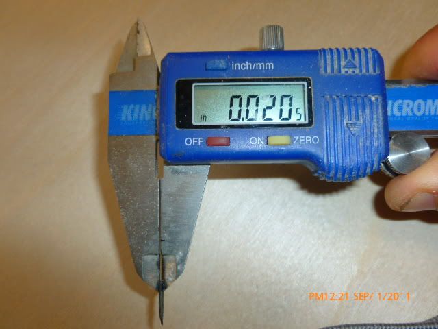
VG Specs ; Inches
Material : .02 Uni Direction carbon laminate.
Thickness : .02
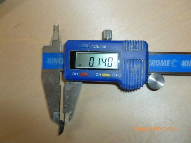
Height : .14
Length : .43
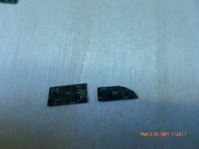
Making them isnt difficult. Use .02 Unidirectional carbon laminates from APC Composites. First step is to start cutting them to length. You can make the carbon strip any length you want.
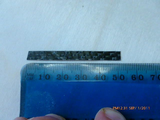
Here we have made a single strip that is taller than it will end up the reason for this is to make it easier to sand and handle, you want to cut them down last.
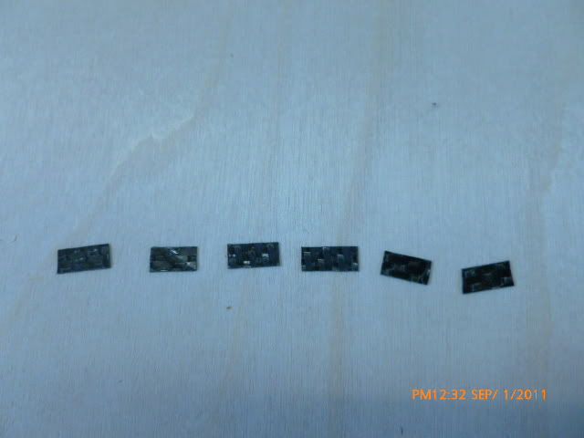
These are cut into basic shapes that are close to the same length of .43 (little over 1 cm) makes for consistent shapes.
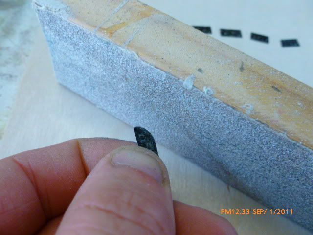
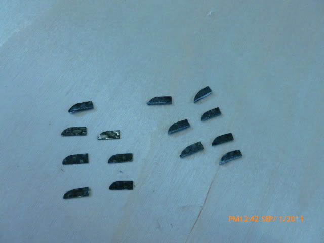
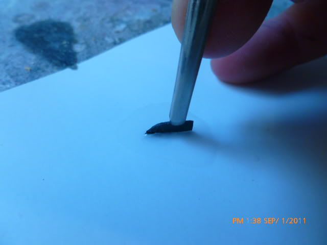
Hand sand the front leading edge shape of the generator. I do this with 120 Grit sandpaper and shape it until its round and they are all accurate / uniform.
Check the height and trim to match.
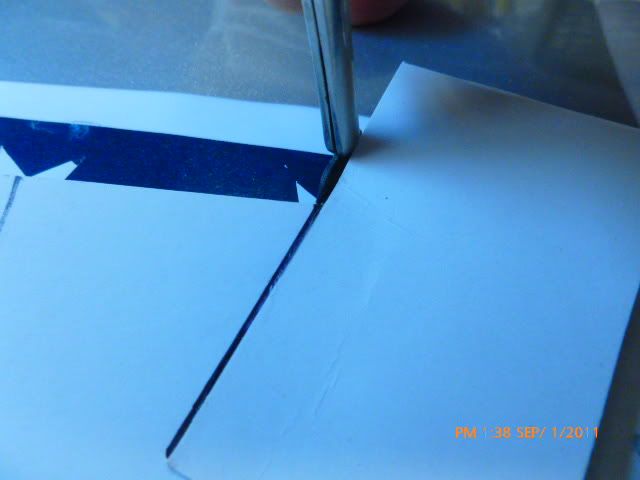
Once I have the shape defined I trim it to the exact height required of .14 this is checked with a vernier. I either sand this or trim it with a sharp blade. You can see below how the 2 are different.
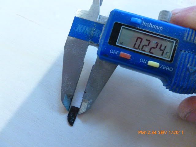
Try to get the heights as accurate as possible, double check each one before you move onto the next. The heights are important for a consistent Vortex, the last thing you want is differences in Vortex energy moving down the wing.
Repeat until you have enough for your project & spares. My latest configuration and the one I suggest people start with are 2 / 8. ( 2 on each surface for a total of 8 )
The critical part of any stunt ship is always alignment. Installing Vortex generators is no exception. I usually do this task at the end of the build, after buffing is completed. Its impossible to buff or sand out a model with the VGs installed before, so do not attempt to fix them before. Simple cleaning and waxing can be done around it after for appearance judging, just be careful.
Place a centre line down the fuselage, this will help to get accurate measurements for the placement of the VGs on both sections of the wings.
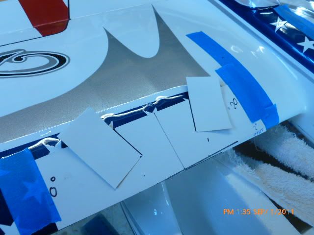
I make up templates for installing the generators the one template is used for the entire model it sets the angles, the distance apart, the distance from the leading edge.
For the latest group of models the distance is as follows: the centre line of the template is 7 ½ inches from the fuselage centre line. The Vortex generators are in total 3 Inches apart from each other Centre line of the template mark outward 1 ½ inches this will be where your Vortex generators start.
Make up this template it helps for alignment and correct placement.
The template is critical to get correct. I make the generators anywhere between 17 degrees and 20 degrees the more angle the more drag. How to align them has always been a concern Do I line it up with the leading edge, or do I line it up 90 degrees to the airflow. I have always felt aligning it to the airflow was correct although I have done both with little measurable differences.
As you can see below the template shows the correct angle. The sweep angle of the leading edge of this specific aircraft is approximately 2 degrees. I factor that into the template so when its sitting on the wing the Generators are at 90 degrees to the airflow.
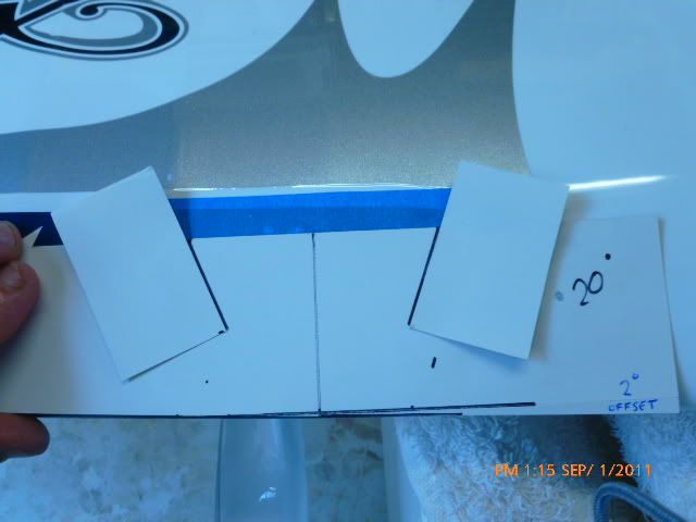
The template is symmetrical The lines on the plane below are used for alignment of the template to a marker: this is to make sure we get them exactly in the same spot in all 4 locations. Note I always join the bottom and top tape lines together to make sure they are accurate.
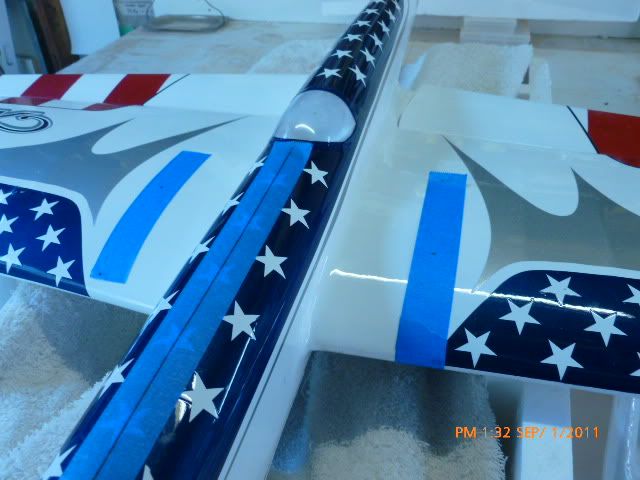
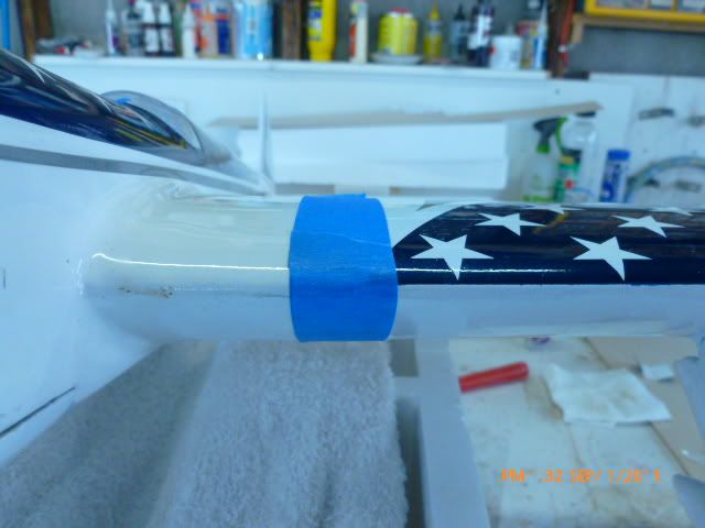
Tape the template to the guide lines. Here you will note the front of the template lines up with the leading edge. Remember to take the sweep angle into account its usually no more than 2 degrees for a normal tapered wing. When you use it on the other side, simply flip the template over and use the reverse for the opposite side.
I use a little pool of CA and dip the end of the generator into it using tweezers carefully apply it to the front of the template. Once the CA has gone off I will then add 1 small drop of medium CA to the carbon, this gives it some strength and resistance to being knocked off. If you simple leave the tiny amount of CA on the bottom they are more prone to being removed.
This is the view from the front here you can see they are perfectly aligned to form a very small X. Even at 20 degrees its very minor but very effective.
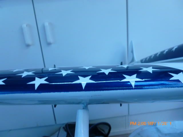
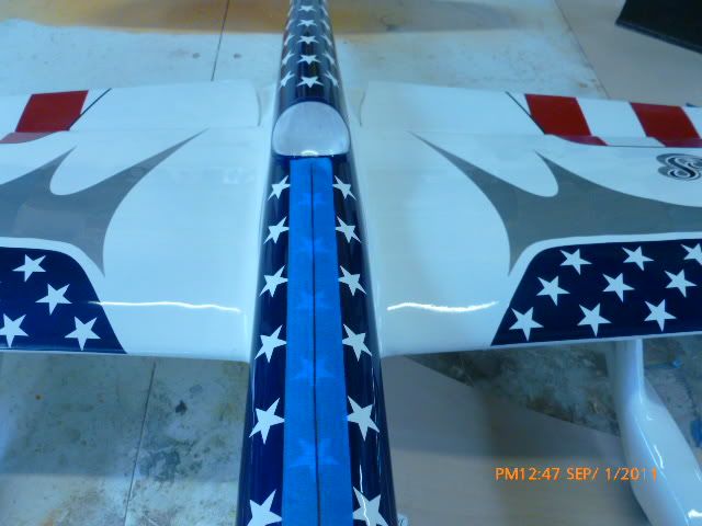
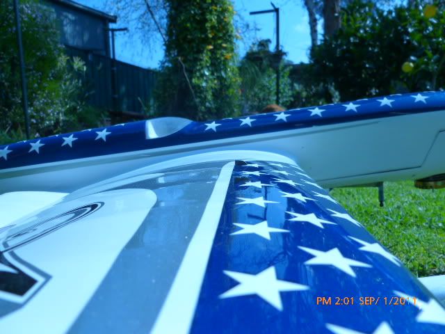
Here is another angle up close of them completed. I intentionally paint the leading edge up that far in part to hide the VG.
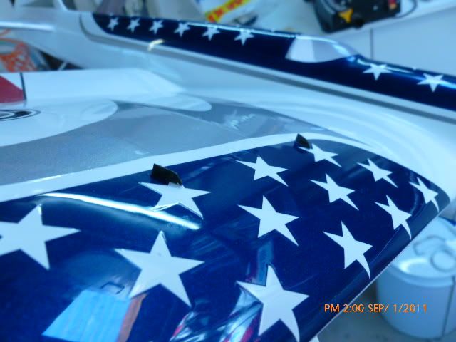
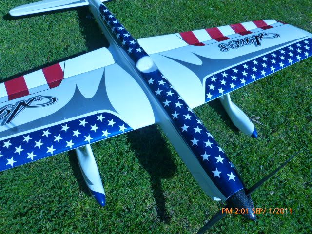
Here is the completed plane with the Vortex Generators installed. Like sealing hinge lines if you do it correctly, its a discrete installation.
Like many things we do in this event its about diversity, trial and error what works for one person might not work for someone else. Pipe or no pipe? Electric or IC ? Nitro or FAI ? Solids or Braided ?
The best thing we can do is share information and hopefully pick up a few hints and tips along the way. I will not build a model without Vortex generator technology included, no different to sealing my hinge lines or running asymmetry on the wing. There have been many designs past and present that achieve success in their own way Spend 2 hours one day on an older model go through the process of installing Vortex Generators as shown and make your own assessments.
If you like it build it into the next model Good luck and keep flying and developing.
P.J Rowland.


 Topic: Vortex Generators - Development and Installation. (Read 22361 times)