News:


  • July 06, 2025, 04:40:53 PM

Login with username, password and session length

Author Topic: Rib Spacing vs Load Distribution  (Read 21159 times)

Offline ash

  • Trade Count: (0)
  • Commander
  • ****
  • Posts: 309
    • I build guitars to pay for CL models!
Rib Spacing vs Load Distribution
« on: November 13, 2011, 03:20:09 PM »
While looking at this picture of Richard Kornemeier's (edit: Frank Wadle, sorry... not Richard Kornemeier!) model at the World Champs I noticed that the ribs are closer together near the fuselage. It's the same on the wing, flaps, stabiliser and elevators.

Presumably the intent of that is to distribute the strength and structure to where the loads are higher. The thing is, I'm not sure if it is actually doing anything in this case. The ribs hold the skin out and take the pressure on the surface, but they don't have much to do with bending loads and torsional loads compared to the LE sheeting and spars.

At first look I thought it was a great idea, but at second look I think a better idea would be to have the ribs evenly spaced and taper the sheeting and spars (in thickness and/or width, whatever suits the structure best). He may well have done that too, but we can't tell from this picture.

So, is there much point in having more ribs in the middle and more space at the tips? Does the pressure distribution on the skin really require more support in the middle?
« Last Edit: November 13, 2011, 04:37:42 PM by ash »
Adrian Hamilton - Auckland, NZ.

Offline Wynn Robins

  • Trade Count: (0)
  • Admiral
  • ******
  • Posts: 1684
Re: Rib Spacing vs Load Distribution
« Reply #1 on: November 13, 2011, 03:51:57 PM »
dunno - but his flap structure looks pretty fricken light!!! 
In the battle of airplane versus ground, the ground is yet to lose

Offline Avaiojet

  • 22 supporter
  • Trade Count: (0)
  • Admiral
  • *
  • Posts: 7468
  • Just here for the fun of it also.
Re: Rib Spacing vs Load Distribution
« Reply #2 on: November 13, 2011, 03:55:56 PM »
Nice looking model from that view.  "Flite Streak" type wing tips.

I'm working on a wing now that has tapered sheeting, tapered spar also. May not be anything to it, but it sure looks good!  n~

"Gimme all the looks baby!"

CB
Trump Derangement Syndrome. TDS. 
Avaiojet Derangement Syndrome. ADS.
Amazing how ignorance can get in the way of the learning process.
If you're Trolled, you know you're doing something right.  Alpha Mike Foxtrot. "No one has ever made a difference by being like everyone else."  Marcus Cordeiro, The "Mark of Excellence," you will not be forgotten. "No amount of evidence will ever persuade an idiot."- Mark Twain. I look at the Forum as a place to contribute and make friends, some view it as a Realm where they could be King.   Proverb 11.9  "With his mouth the Godless destroys his neighbor..."  "Perhaps the greatest challenge in modeling is to build a competitive control line stunter that looks like a real airplane." David McCellan, 1980.

Offline Lauri Malila

  • Trade Count: (0)
  • Admiral
  • ******
  • Posts: 1738
Re: Rib Spacing vs Load Distribution
« Reply #3 on: November 13, 2011, 04:18:40 PM »
 Hi.

 That's not Richie but Frank Wadle.
 We do the same thing with rib spacing in Free flight, plus that I reinforce the about 10 rootmost ribs sides with +-45 degr. glassfiber. The root ribs are usually the first thing that fails in a strong launch; High tension in towline (up to 30kp) bends wingtips up, and that causes the t.e. to compress against the ribs. At some point the carbon capstrips collapse and the model becomes unflyable.
 I cannot see why the same mechanism would not apply to a stunt wing. Of course, the wing is not thin & undercamber but the amount of stress the wing must handle is about the same.
 And Franks flaps are the stiffest I've ever seen! Very cool torque tubes. Lauri

Offline john e. holliday

  • 25 supporter
  • Trade Count: (0)
  • Admiral
  • *
  • Posts: 22989
Re: Rib Spacing vs Load Distribution
« Reply #4 on: November 13, 2011, 04:29:06 PM »
Take a look at the ISW(International Stunt Winner) wing construction some time.   I think Walter has the plans on his site as well as the construction photos.  Very light and stiff.
John E. "DOC" Holliday
10421 West 56th Terrace
Shawnee, KANSAS  66203
AMA 23530  Have fun as I have and I am still breaking a record.

Offline PJ Rowland

  • AUS - 29541 AMA - 809970
  • Trade Count: (0)
  • Admiral
  • ******
  • Posts: 2056
  • Melbourne - AUSTRALIA
Re: Rib Spacing vs Load Distribution
« Reply #5 on: November 13, 2011, 07:22:04 PM »
What cannot be seen from this photo is if there is any use of Shear Web between the ribs.

If you always put limit on everything you do, physical or anything else. It will spread into your work and into your life. There are no limits. There are only plateaus, and you must not stay there, you must go beyond them.” - Bruce Lee.

...
 I Yearn for a world where chickens can cross the road without having their motives questioned.

Offline Randy Powell

  • 21 supporter
  • Trade Count: (0)
  • Admiral
  • *
  • Posts: 10476
  • TreeTop Flyer
Re: Rib Spacing vs Load Distribution
« Reply #6 on: November 13, 2011, 08:08:28 PM »
Well, the classic plane I'm building didn't worry about that. The ribs are 7/8" apart ... all the way to the tip. 28 ribs inboard, 27 outboard.   HB~>
Member in good standing of P.I.S.T
(Politically Incorrect Stunt Team)
AMA 67711
 Randy Powell

Offline Larry Cunningham

  • Red Hot Lover
  • Trade Count: (0)
  • Captain
  • *****
  • Posts: 855
  • Klaatu barada nikto my ass
    • Stephanie Miller
Re: Rib Spacing vs Load Distribution
« Reply #7 on: November 13, 2011, 08:48:07 PM »
I'm inclined to agree that it doesn't make much sense as a structural feature. But it looks very good!

Appearance is a worthwhile reason for doing it. It's a nice looking model.

L.

"True friends stab you in the front." -Oscar Wilde
AMA 247439 - '09, '10, '11, '12 and '13 Supporter of this site..

Offline Larry Cunningham

  • Red Hot Lover
  • Trade Count: (0)
  • Captain
  • *****
  • Posts: 855
  • Klaatu barada nikto my ass
    • Stephanie Miller
Re: Rib Spacing vs Load Distribution
« Reply #8 on: November 13, 2011, 08:51:12 PM »
Well, the classic plane I'm building didn't worry about that. The ribs are 7/8" apart ... all the way to the tip. 28 ribs inboard, 27 outboard.   HB~>

Hi Randy,

Sounds like a Minado to me. Am I close?

L.

"Design is not just what it looks like and feels like. Design is how it works." -Steve Jobs
AMA 247439 - '09, '10, '11, '12 and '13 Supporter of this site..

Offline Steve Helmick

  • 24 supporter
  • Trade Count: (0)
  • Admiral
  • *
  • Posts: 10267
Re: Rib Spacing vs Load Distribution
« Reply #9 on: November 13, 2011, 10:40:33 PM »
By supporting the sheeted LE with closer rib spacing, the strength and stiffness near the center of the wing would be improved, and wider spacing at the tips would save weight and reduce weight at the tips, which I think is a valid design goal.

FWIW, one clever guy I read about in SN curved his fuselage sides to improve the stiffness...that would be Larry Cunningham. Personally, I think the uneven rib spacing looks flaky, but this is obviously for F2B, so no appearance point issues.   H^^ Steve 
"The United States has become a place where professional athletes and entertainers are mistaken for people of importance." - Robert Heinlein

In 1944 18-20 year old's stormed beaches, and parachuted behind enemy lines to almost certain death.  In 2015 18-20 year old's need safe zones so people don't hurt their feelings.

Offline Hoss Cain

  • 2015
  • Trade Count: (0)
  • Captain
  • *
  • Posts: 447
Re: Rib Spacing vs Load Distribution
« Reply #10 on: November 13, 2011, 11:12:07 PM »
I'm inclined to agree that it doesn't make much sense as a structural feature. But it looks very good!

Appearance is a worthwhile reason for doing it. It's a nice looking model.
L.

Personally, I differ with you. When a wing breaks from load abuse, it generally happens in the center portion of the wing simply because that is where the load is manifested. In the older airliners - the ones that I flew - there were limitations on distributing wing fuel so as to keep fuel in the outboard tanks so as to not allow the wing to bend upwards too much during flight. In the OLLDD USAF, the B-47 did not have in-wing fuel so the bending of the wing was allowed up to 27 ft at the wing tip. After that it probably would desert the airplane. During LABS maneuvers - a system to come off the deck and toss a Nuke at about 18,000 ft - a number of airplanes did shed a wing and that was at the fuselage. Kinda messes up your plans for later in the day. Once they rebuilt the wing mounting, we quit doing that maneuver because the Thermo Nukes required better distance procedures.
I have often wondered why CL Stunt designs did not build stronger structures inboard and lighter at the outer 1/3rd +/-. Maybe it's just that the guy won the last contest with XXXX therefore my new design will be like that one, syndrome.

I think that design pictured is way ahead of the average stunter. Those carbon tubes are very stiff.

Quote
What cannot be seen from this photo is if there is any use of Shear Web between the ribs.

Look closely and a thin strip of rib is under the capstrip, top and bottom. Then looking at the inner core under the spars, one can see what looks like the rib becoming solid forward. In addition sheer webs may do better for preventing wing twist, however for bending under load, a 1/16 -3/32 X 1/2 against ribs or so will do as well as a complete section between ribs. Worked for me in C FF, CL stunters, Q-500 Pylon and Scale Warbird Racing.
Horrace Cain
AMA L-93 CD and Leader
New Caney, TX  (NE Houston area)

Offline Howard Rush

  • 25 supporter
  • Trade Count: (0)
  • Admiral
  • *
  • Posts: 7980
Re: Rib Spacing vs Load Distribution
« Reply #11 on: November 14, 2011, 02:15:34 AM »
...for bending under load, a 1/16 -3/32 X 1/2 against ribs or so will do as well as a complete section between ribs. Worked for me in C FF, CL stunters, Q-500 Pylon and Scale Warbird Racing.

Let's see your analysis of that one. 
The Jive Combat Team
Making combat and stunt great again

Offline PerttiMe

  • Trade Count: (0)
  • Admiral
  • ******
  • Posts: 1183
Re: Rib Spacing vs Load Distribution
« Reply #12 on: November 14, 2011, 05:26:12 AM »
What cannot be seen from this photo is if there is any use of Shear Web between the ribs.

Here's a different angle.
(photo from Claudia Kehnen's gallery on flickr)
http://www.flickr.com/photos/fesselflug/sets/72157604344596607/with/2379408497/
I built a Blue Pants as a kid. Wish I still had it. Might even learn to fly it.

Online John Miller

  • 25 supporter
  • Trade Count: (0)
  • Admiral
  • *
  • Posts: 1728
Re: Rib Spacing vs Load Distribution
« Reply #13 on: November 14, 2011, 06:35:39 AM »
By closing up the rib spacing as you get nearer to the fuselage sides does do at least one thing that is favorable as I see it. By making the unsupported length of the spars shorter between the supports, (ribs) helps control the flex possible in the unsupported span. Coupled with the truss style webbing will make the center section of the wing much stronger, where it's needed. Out, as you approach the tips, the load isn't concentrated, so there's less tendency to flex.

I once applied a strip of CF to the top side of the spar. Not a good idea. The spars flexed enough that the glue bond between the CF and the spar failed. This made for a noticably weakened wing. I later found that in such cases, the CF should be lamionated between two pieces of spar material. H^^
Getting a line on life. AMA 1601

Offline Avaiojet

  • 22 supporter
  • Trade Count: (0)
  • Admiral
  • *
  • Posts: 7468
  • Just here for the fun of it also.
Re: Rib Spacing vs Load Distribution
« Reply #14 on: November 14, 2011, 08:25:04 AM »
Do I see carbon footprints in some areas?

I'd like to know more about his use of carbon. That can't be just black paint?

Great craftsmanship for sure!

CB
Trump Derangement Syndrome. TDS. 
Avaiojet Derangement Syndrome. ADS.
Amazing how ignorance can get in the way of the learning process.
If you're Trolled, you know you're doing something right.  Alpha Mike Foxtrot. "No one has ever made a difference by being like everyone else."  Marcus Cordeiro, The "Mark of Excellence," you will not be forgotten. "No amount of evidence will ever persuade an idiot."- Mark Twain. I look at the Forum as a place to contribute and make friends, some view it as a Realm where they could be King.   Proverb 11.9  "With his mouth the Godless destroys his neighbor..."  "Perhaps the greatest challenge in modeling is to build a competitive control line stunter that looks like a real airplane." David McCellan, 1980.

Offline john e. holliday

  • 25 supporter
  • Trade Count: (0)
  • Admiral
  • *
  • Posts: 22989
Re: Rib Spacing vs Load Distribution
« Reply #15 on: November 14, 2011, 09:11:27 AM »
As I showed a flying partner one time.   Iron on coverings such as Mono-Kote are just as stiff as the other coverings if done right.  Have to get the iron hot enough.  I turn the iron up until the covering disappears if held in one spot too long.   Then back off a bit.I have personally seen wing flex in planes in which silk, silk span and a few others in which they flexed because not enough dope was applied.   One old timer told me once, "If the wing is too stiff it will break easier".   Never argued with him. H^^
John E. "DOC" Holliday
10421 West 56th Terrace
Shawnee, KANSAS  66203
AMA 23530  Have fun as I have and I am still breaking a record.

Offline Hoss Cain

  • 2015
  • Trade Count: (0)
  • Captain
  • *
  • Posts: 447
Re: Rib Spacing vs Load Distribution
« Reply #16 on: November 14, 2011, 09:52:50 AM »
Let's see your analysis of that one. 

Sorry, Howard, I don't need "analysis" in toy airplanes other than Center of Gravity and I already have some of those.  As far as the structure supports go, I just look it over, decide where things should be, try it and if it works it was good, if not I try again.  :##

Let the "Injun-Ears" play with the "analysis". After all they get paid well to change things every few months. When things go wrong like not placing fuel boost pumps in a sump, and airplanes start blowing up when fuel transfers are in operation, well those doing "analysis" just have more job security.  %^@

I have flown 1:1 scale airplanes 20 years old and modifications are still coming down the pike.

OTOH I do do analysis on personal actions like why a politician acts as he/she does and that is usually that the action is to favor the largest $$$ donator.  y1
Horrace Cain
AMA L-93 CD and Leader
New Caney, TX  (NE Houston area)

Offline billbyles

  • AMA Member
  • Trade Count: (0)
  • Captain
  • *
  • Posts: 648
Re: Rib Spacing vs Load Distribution
« Reply #17 on: November 14, 2011, 12:12:14 PM »

<snip>

 In the older airliners - the ones that I flew - there were limitations on distributing wing fuel so as to keep fuel in the outboard tanks so as to not allow the wing to bend upwards too much during flight.

Generally, one of the benefits of putting fuel in the outer wing tanks/wing tip tanks is inertia relief during turbulence encountered in flight.  As an engineer and commercial pilot I never heard of "not allowing the wing to bend upwards too much in flight" (except by careful structural design).

I have often wondered why CL Stunt designs did not build stronger structures inboard and lighter at the outer 1/3rd +/-.

That has happened beginning a long time ago in very simple ways - one way to do it is to put shear webs between the top & bottom spars for about 2/3 of the way out.

Maybe it's just that the guy won the last contest with XXXX therefore my new design will be like that one, syndrome.

Seems like most designs in every field kinda build on the preceding ones.

<snip>

In addition sheer webs may do better for preventing wing twist, however for bending under load, a 1/16 -3/32 X 1/2 against ribs or so will do as well as a complete section between ribs.

Like Howard, I'd like to see your analysis on that one.
Bill Byles
AMA 20913
So. Cal.

Offline billbyles

  • AMA Member
  • Trade Count: (0)
  • Captain
  • *
  • Posts: 648
Re: Rib Spacing vs Load Distribution
« Reply #18 on: November 14, 2011, 12:26:22 PM »

Sorry, Howard, I don't need "analysis" in toy airplanes other than Center of Gravity and I already have some of those.  As far as the structure supports go, I just look it over, decide where things should be, try it and if it works it was good, if not I try again.  :##

Let the "Injun-Ears" play with the "analysis". After all they get paid well to change things every few months. When things go wrong like not placing fuel boost pumps in a sump, and airplanes start blowing up when fuel transfers are in operation, well those doing "analysis" just have more job security.  %^@

I have flown 1:1 scale airplanes 20 years old and modifications are still coming down the pike.

<snip>

With your "kick the tires, light the fires, brief on guard, & last one airborne buys the beer" mentality I'm glad I wasn't flying on airliners when you were still in the left seat.  Reading your posts I have no doubt that you could easily design the best airliner in existence from the ground up in detail since they are such a simple piece of equipment.
Bill Byles
AMA 20913
So. Cal.

Offline Brett Buck

  • Trade Count: (0)
  • Admiral
  • ******
  • Posts: 14501
Re: Rib Spacing vs Load Distribution
« Reply #19 on: November 14, 2011, 01:05:48 PM »
As I showed a flying partner one time.   Iron on coverings such as Mono-Kote are just as stiff as the other coverings if done right. 

   No, it isn't. Not even close. I am one of the few people to make the Top 20 and I still may have the highest NATS appearance scores with Monokote, so I have some knowledge of the topic.

   Even heated to the ultimate, even the good old Monokote was very much less stiff than GM silkspan and dope. I did some tests with it and even on solid structures you lost a lot of rigidity with monokote over conventional covering. It may get better over time as the Monokote turns to glass due to UV exposure and leaching of the plasticizers, but when it gets to that point it starts shattering on impact (or even when you are cleaning it), too.

   The loss of rigidity has been overstated over the years, but its definitely not as stiff as a conventional silkspan and dope finish with a reasonable amount of plasticizer.

   As near as I can tell, all of the current non-Monokote products are substantially softer and provide less rigidity than even Monokote. The same effect that makes them easy to work with also makes them unable to provide the same stability to the structure.

    This is not necessarily a bad thing, because there are also advantages, but you *do* have to know about it and *do* have to consider it in the design.

    Brett

Offline Brett Buck

  • Trade Count: (0)
  • Admiral
  • ******
  • Posts: 14501
Re: Rib Spacing vs Load Distribution
« Reply #20 on: November 14, 2011, 01:26:54 PM »
Sorry, Howard, I don't need "analysis" in toy airplanes other than Center of Gravity and I already have some of those.  As far as the structure supports go, I just look it over, decide where things should be, try it and if it works it was good, if not I try again.  :##


  That's swell as long as your goal is sport flying. Try "cut and try" exclusively in stunt competition, see how that works out for you. It doesn't always take the form of lengthy calculations but *everybody*, and I mean *everybody* who is the least bit successful spends most of their time on analysis to varying degrees. And while it may be more obvious today (given that everyone has access to many top fliers at their fingertips) I don't think it has ever been a lot different from that.

   We get a lot of friction at times because there is a huge range of skills and goals all posting on the same boards and in the same magazine. The question asked here is an example of something that sport fliers, to first approximation, don't have to care about. That doesn't mean it's a stupid question and it doesn't mean it deserves no answer because *you* don't happen to care about the right answer.

   And, the right answer is, closer rib spacing helps *marginally* by providing more stability to the wing covering and LE sheeting to reduce the chances of it buckling when in compression. But is almost certainly much less effective (in terms of added strength VS added weight) than a lot of the other items mentioned, like beefing up the spars near the root, make the sheeting thicker (or double-covering, although that has other issues), etc, that put the extra weight near the wing surface.

   If you were to taper the LE sheeting from maybe 3/16" at the root to 1/32" a the tip, for example, that would likely be a much more efficient use of materials for a given weight, at least to mitigate flight loads. Howard could even figure out what the thickness profile should be as a function of the span, if he were so inclined. It might be impractical but it's a useful thought experiment.

    Brett

Offline Robert-Jan

  • Trade Count: (0)
  • Lieutenant
  • ***
  • Posts: 93

Offline Howard Rush

  • 25 supporter
  • Trade Count: (0)
  • Admiral
  • *
  • Posts: 7980
Re: Rib Spacing vs Load Distribution
« Reply #22 on: November 14, 2011, 02:25:22 PM »
Enjoy,

http://fesselflugcenter.kostenloses-forum.be/fesselflugcenter-beitrag97.html&highlight=

greetings Robert-Jan

Wow.  That's really cool. 

I am a monolingual, at best, American, so I don't understand what's being written there, but it appears that those people are even nastier toward each other than we are.  For example, in Frank's last post, he seems to accuse somebody of having Balsa benutzt, then goes on to worse.
The Jive Combat Team
Making combat and stunt great again

Offline ash

  • Trade Count: (0)
  • Commander
  • ****
  • Posts: 309
    • I build guitars to pay for CL models!
Re: Rib Spacing vs Load Distribution
« Reply #23 on: November 14, 2011, 02:33:08 PM »
Thanks for all the comments, guys... for the name correction, Lauri... and for the build-diary link, Robert-Jan.

After a bit more thinking and comments/ideas from others, my thinking pretty much exactly matches Brett's as quoted below. Somewhere between my first and second positions. Frank's build thread shows that he's a very good builder and I'll be taking some inspiration from those images when my next stunt build comes up.

A bit of Googling yesterday revealed the model weight tables from the World Champs where this picture was taken. Franks models weighed 1600g (56.4oz), equal lightest of the tournament.


    And, the right answer is, closer rib spacing helps *marginally* by providing more stability to the wing covering and LE sheeting to reduce the chances of it buckling when in compression. But is almost certainly much less effective (in terms of added strength VS added weight) than a lot of the other items mentioned, like beefing up the spars near the root, make the sheeting thicker (or double-covering, although that has other issues), etc, that put the extra weight near the wing surface.

   If you were to taper the LE sheeting from maybe 3/16" at the root to 1/32" a the tip, for example, that would likely be a much more efficient use of materials for a given weight, at least to mitigate flight loads. Howard could even figure out what the thickness profile should be as a function of the span, if he were so inclined. It might be impractical but it's a useful thought experiment.

    Brett
Adrian Hamilton - Auckland, NZ.

Offline PerttiMe

  • Trade Count: (0)
  • Admiral
  • ******
  • Posts: 1183
Re: Rib Spacing vs Load Distribution
« Reply #24 on: November 14, 2011, 02:38:09 PM »
For example, in Frank's last post, he seems to accuse somebody of having Balsa benutzt, then goes on to worse.
Nono, even I could understand that he confesses that "CFK-Profil welches ich zur Verstärkung des Balsa benutzt habe ist ca. 0,4mm dick ". He has used a carbon strip to reinforce his balsa!

(and it is only the last post of the first page  VD~ )
I built a Blue Pants as a kid. Wish I still had it. Might even learn to fly it.

Offline Howard Rush

  • 25 supporter
  • Trade Count: (0)
  • Admiral
  • *
  • Posts: 7980
Re: Rib Spacing vs Load Distribution
« Reply #25 on: November 14, 2011, 02:48:50 PM »
Oh.
The Jive Combat Team
Making combat and stunt great again

Offline Chris Wilson

  • Trade Count: (0)
  • Admiral
  • ******
  • Posts: 1710
Re: Rib Spacing vs Load Distribution
« Reply #26 on: November 14, 2011, 07:01:03 PM »
Thanks for all the comments, guys... for the name correction, Lauri... and for the build-diary link, Robert-Jan.

After a bit more thinking and comments/ideas from others, my thinking pretty much exactly matches Brett's as quoted below. Somewhere between my first and second positions. Frank's build thread shows that he's a very good builder and I'll be taking some inspiration from those images when my next stunt build comes up.

A bit of Googling yesterday revealed the model weight tables from the World Champs where this picture was taken. Franks models weighed 1600g (56.4oz), equal lightest of the tournament.


Ash, you going to post the conclusions back over at Barton mate?

It seems that the 'extra' ribs do no more harm than good and could possibly be a signature thing.
MAAA AUS 73427

You have enemies? Good. That means you've stood up for something, sometime in your life.
 Nothing in life is so exhilarating as to be shot at without result.  It's not enough that we do our best; sometimes we have to do what's required

Online Mike Scholtes

  • Trade Count: (0)
  • Admiral
  • ******
  • Posts: 1199
Re: Rib Spacing vs Load Distribution
« Reply #27 on: November 14, 2011, 08:00:04 PM »
I commend the link to the German post by Robert-Jan just to see the CNC-machined carbon cloth 2-piece bellcrank! Plus all the wing ribs are CNC milled, not laser cut. This build article appears to be from 2006 so the methods may have changed since then. No need to understand German to enjoy the article. LOTS of FF technique on display, especially the flaps and elevators. This is the stunter Walt Ghio would build!

Interesting to see the comments and questions from other builders, mostly about whether he built or purchased various items and how stuff is made.

Offline Avaiojet

  • 22 supporter
  • Trade Count: (0)
  • Admiral
  • *
  • Posts: 7468
  • Just here for the fun of it also.
Re: Rib Spacing vs Load Distribution
« Reply #28 on: November 15, 2011, 07:36:04 AM »
Enjoy,http://fesselflugcenter.kostenloses-forum.be/fesselflugcenter-beitrag97.html&highlight=greetings Robert-Jan

Well, Robert,

Thanks for that great and informative site. Answers many questions I don't have to search for to get the answers to?

Got a parts list and source? Yea, I know, I'm stretching it.   n~

Thanks,

CB
Trump Derangement Syndrome. TDS. 
Avaiojet Derangement Syndrome. ADS.
Amazing how ignorance can get in the way of the learning process.
If you're Trolled, you know you're doing something right.  Alpha Mike Foxtrot. "No one has ever made a difference by being like everyone else."  Marcus Cordeiro, The "Mark of Excellence," you will not be forgotten. "No amount of evidence will ever persuade an idiot."- Mark Twain. I look at the Forum as a place to contribute and make friends, some view it as a Realm where they could be King.   Proverb 11.9  "With his mouth the Godless destroys his neighbor..."  "Perhaps the greatest challenge in modeling is to build a competitive control line stunter that looks like a real airplane." David McCellan, 1980.

Offline john e. holliday

  • 25 supporter
  • Trade Count: (0)
  • Admiral
  • *
  • Posts: 22989
Re: Rib Spacing vs Load Distribution
« Reply #29 on: November 15, 2011, 08:52:03 AM »
Who needs to know the language when there are the pictures.   He is a craftsman.   H^^
John E. "DOC" Holliday
10421 West 56th Terrace
Shawnee, KANSAS  66203
AMA 23530  Have fun as I have and I am still breaking a record.

Offline Frank Wadle

  • Trade Count: (0)
  • Lieutenant
  • ***
  • Posts: 65
Re: Rib Spacing vs Load Distribution
« Reply #30 on: November 16, 2011, 03:47:58 AM »
Hello everybody!

First I would like to thank everybody for your positive feedback on my plane!

After reading this thread about one of my planes, I thought it would be time to register to this forum and comment some things discussed.

The first picture in this thread shows me an my Plane "Big Kahuna 1" (BK!) at the EC 2011 in Poland.
This plane was the second "serious" stunter that I've built. The build of this model was covered in a thread at the German forum (see link above).
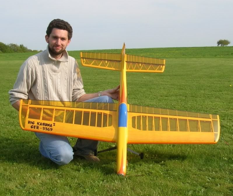
Two years after BK1 I started to build an improved version "Big Kahuna 2" (BK2). Modifications included (but were not limited to) more strength and stiffness by using more carbon fiber. Both planes BK1 and BK2 were used at the 2009 EC, 2010 WC and 2011 EC and will most likely be used next year for the 2012 WC.

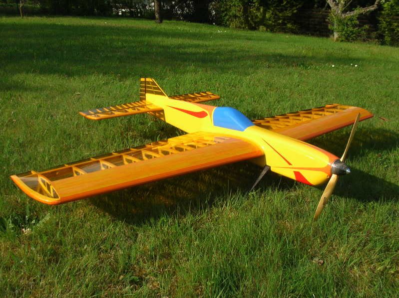
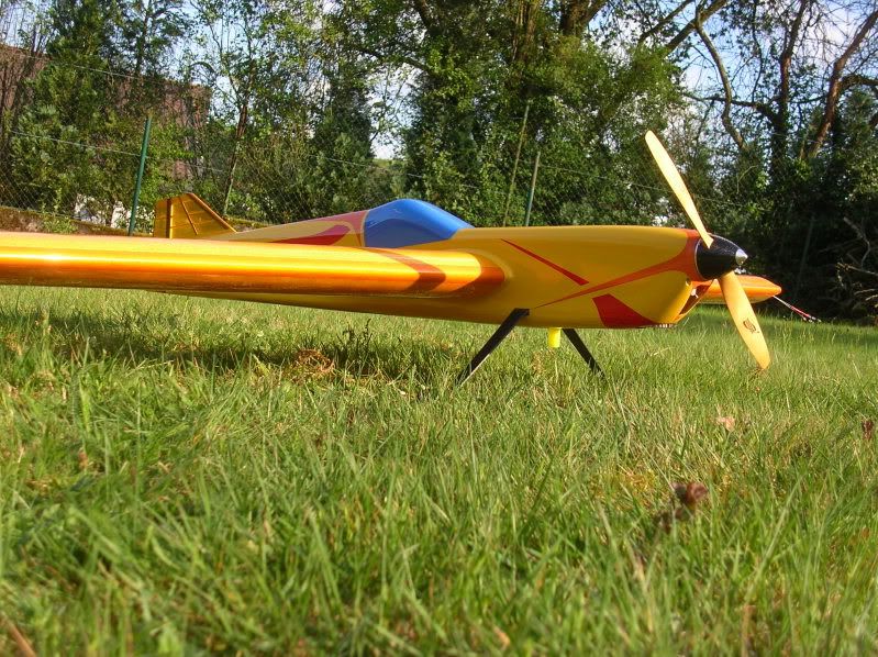
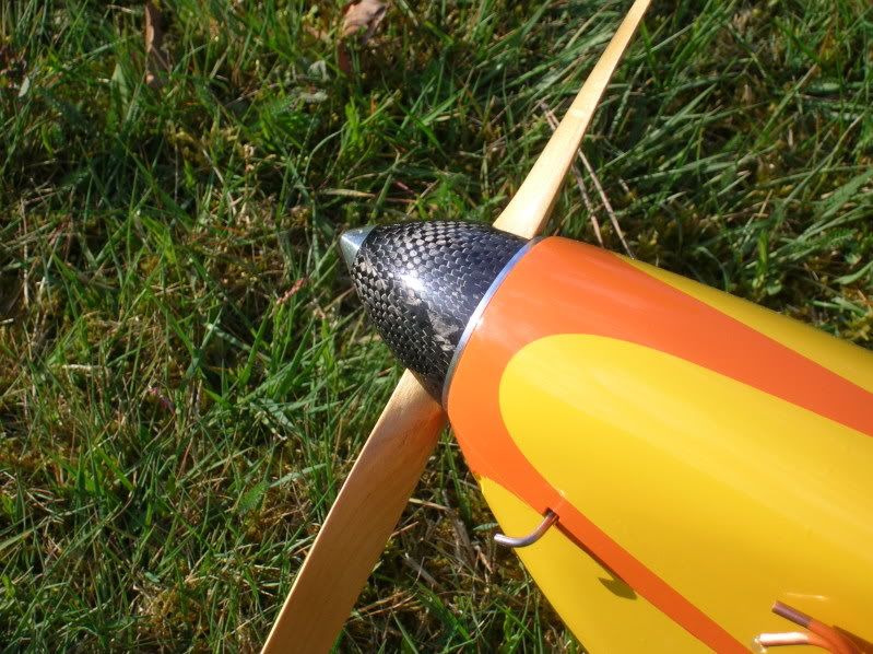
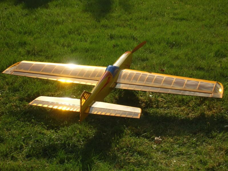
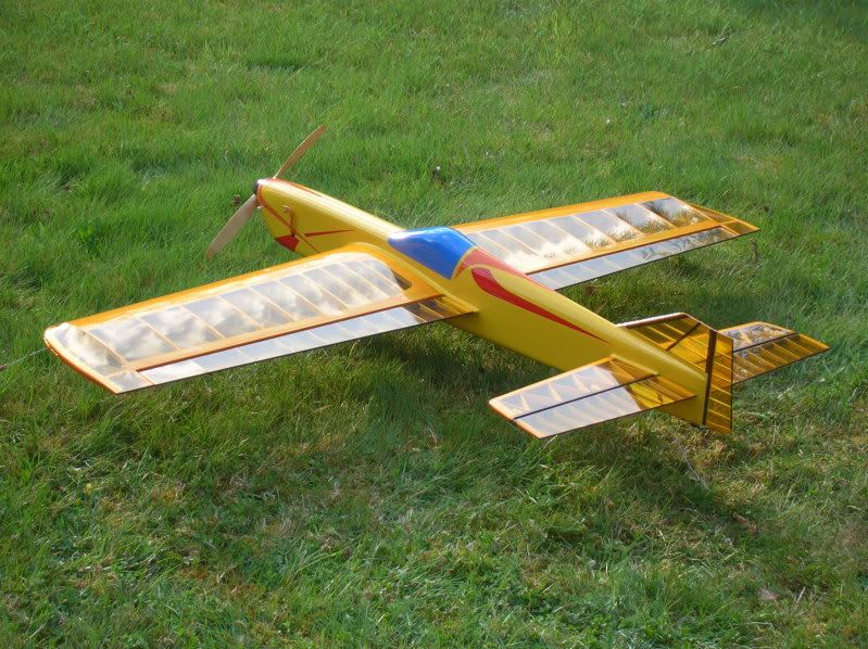
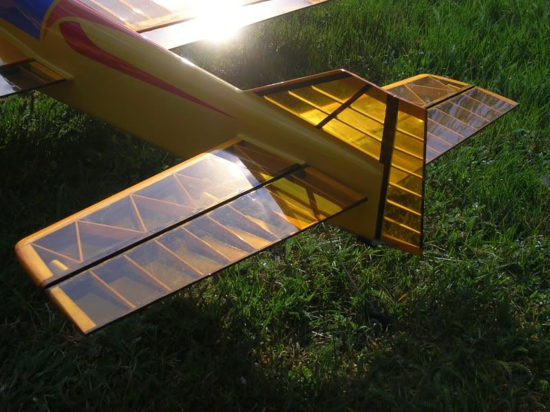
Here are some pics of BK2:


Here are my comments on some topics of this thread:

Why did I chose the unequal rib spacing?
1. It looks cool!!!!
2. I've not seen it before in F2B
3. It makes the planking at the root a bit stronger by supporting it. My first plane (Blackadder) got damaged when someone tried to hold it at the wing and broke the planking at the root with his fingers.
4. I designed the Wing in CAD and cut the ribs on a CNC machine. That means: Unequal rib spacing is just as easy to do as an equal spacing.

Does it add strength or stiffness?
I think it does. But I think the difference is small. To small to overcome the loss in stiffness and strength by using Oracover (German Monokote) instead of silk.

So why did I use plastic film instead of silk?
Because I think it looks cool :-)


I would also like to comment the weight.
Big Kahuna 1 (BK1) weights ~1580g (~55.7oz); BK2 is a bit heavier at ~1620g (~57.1oz). I think that is to light for such a big wing!!!! I don't know the wing area, but it was one of the bigger planes of the WC and EC and it was one of the lightest planes. It is like a feather in the wind. Every hiccup of the engine is instantly converted to a change in speed. Every gust and turbulence causes the plane to jump around. It is maneuverable, but far not as rock steady as other planes. It looks like Speedy Gonzales is trapped inside the plane, jumping up and down and round and round all the time.

Also: The light and stiff structure along with the Oracover film makes the plane very loud! Spectators report that, as soon as the bottom or upper side of the wing is visible (in a maneuver) the noise triples. Luckily the judges don't get to hear that much :-)

I love both planes and I hope they serve me well for the next years.

I'm curious what you guys are commenting now. I can't wait to read upcoming posts :-)

With kind regards
Frank

+ Sorry for possible spelling errors!

Offline Luiz Carlos Franco

  • Trade Count: (0)
  • Ensign
  • **
  • Posts: 32
Re: Rib Spacing vs Load Distribution
« Reply #31 on: November 16, 2011, 04:55:00 AM »
Beautifull work, Frank!
As for the name (Kahuna), I googled it and seems to be an Hawaian Sorcerer.
Is that the origin or as with the clear oracover, it "sounded cool !!"  #^ #^
Congratulations again

Luiz

Offline Avaiojet

  • 22 supporter
  • Trade Count: (0)
  • Admiral
  • *
  • Posts: 7468
  • Just here for the fun of it also.
Re: Rib Spacing vs Load Distribution
« Reply #32 on: November 16, 2011, 06:36:41 AM »
I feel sick, look how young that guy is.  

If we team up and really try, maybe we can find something to pick apart?  ;D

Kudos on that build.

Gee, ya want some free "CFC Graphics" on that model?

CB

Trump Derangement Syndrome. TDS. 
Avaiojet Derangement Syndrome. ADS.
Amazing how ignorance can get in the way of the learning process.
If you're Trolled, you know you're doing something right.  Alpha Mike Foxtrot. "No one has ever made a difference by being like everyone else."  Marcus Cordeiro, The "Mark of Excellence," you will not be forgotten. "No amount of evidence will ever persuade an idiot."- Mark Twain. I look at the Forum as a place to contribute and make friends, some view it as a Realm where they could be King.   Proverb 11.9  "With his mouth the Godless destroys his neighbor..."  "Perhaps the greatest challenge in modeling is to build a competitive control line stunter that looks like a real airplane." David McCellan, 1980.

Offline ash

  • Trade Count: (0)
  • Commander
  • ****
  • Posts: 309
    • I build guitars to pay for CL models!
Re: Rib Spacing vs Load Distribution
« Reply #33 on: November 16, 2011, 07:07:27 AM »
Hi Frank. Thanks for joining in with more pictures!

The burning question in my mind is, where do you get the carbon fibre tubes you use for the flaps and elevators? I have never seen CF tubes that size with the 45 degree fibre orientation except for those that were custom made.

What is the engine in the BK2?
Adrian Hamilton - Auckland, NZ.

Offline Allan Perret

  • 2017
  • Trade Count: (0)
  • Admiral
  • *
  • Posts: 1892
  • Proverbs
Re: Rib Spacing vs Load Distribution
« Reply #34 on: November 16, 2011, 08:08:03 AM »
I too am interested in the flap and elevator construction.  Anyway you could translate the parts of the linked construction thread above that cover those items.
Allan Perret
AMA 302406
Slidell, Louisiana

Offline john e. holliday

  • 25 supporter
  • Trade Count: (0)
  • Admiral
  • *
  • Posts: 22989
Re: Rib Spacing vs Load Distribution
« Reply #35 on: November 16, 2011, 08:31:40 AM »
If I could build like that, I would use the transparent coverings.    But, I use poly-ester cloth that is semi-transparent.   Silk is way to expensive for me.   Yes, I am a cheap skate.   Also both planes are gorgeous.   H^^
John E. "DOC" Holliday
10421 West 56th Terrace
Shawnee, KANSAS  66203
AMA 23530  Have fun as I have and I am still breaking a record.

Offline PerttiMe

  • Trade Count: (0)
  • Admiral
  • ******
  • Posts: 1183
Re: Rib Spacing vs Load Distribution
« Reply #36 on: November 16, 2011, 08:45:33 AM »
I recall there have been long discussions on what it takes to get the airplane to behave in difficult winds...
I built a Blue Pants as a kid. Wish I still had it. Might even learn to fly it.

Offline Larry Cunningham

  • Red Hot Lover
  • Trade Count: (0)
  • Captain
  • *****
  • Posts: 855
  • Klaatu barada nikto my ass
    • Stephanie Miller
Re: Rib Spacing vs Load Distribution
« Reply #37 on: November 16, 2011, 09:17:00 AM »
Hmmm.. So you did it because it "looks cool", huh!

It does look cool, the entire model is boss. Beautiful job.

I'll bet it flies like a champ as well.

Best regards,

L.

"My theory is that all of Scottish cuisine is based on a dare." -Mike Myers
AMA 247439 - '09, '10, '11, '12 and '13 Supporter of this site..

Offline Frank Wadle

  • Trade Count: (0)
  • Lieutenant
  • ***
  • Posts: 65
Re: Rib Spacing vs Load Distribution
« Reply #38 on: November 16, 2011, 11:33:54 AM »
Thanks for the commendations, guys   b1

Let me answer the questions on the Flap / Elevator design.
The carbon tube used is, lets call is "homemade" :-)
I'm working for a company manufacturing such tubes on a filament winding machine. Every tube we make is custom made, so don't ask me about price. They are VERY EXPENSIVE!!! Go google for "filament winding" and you'll see that it is possible to make such tubes at home.
The inner diameter is 10mm, the outer diameter is 10,8mm. The fibers are orientated under 45°, giving maximum torque stiffness.
Each flap has 3 "hinges":
First I made little cylindrical parts from Teflon, diameter 9,8mm and 20mm long. Each of the Teflon pieces gets a lateral hole for a M3 screw. The carbon tube has a lateral slot of 3,5mm for every hinge. Now the Teflon cylinder is pushed into the tube so that the hole in the Teflon and the slot in the are aligned. Then a M3 screw is screwed into the hole and the head of the tube is removed..... That's it :-)


The part of the screw that sticks out is glued into the trailing edge of the wing. Now the tube can rotate around the Teflon +-30°, depending on the width of the slot.


The ribs of the flap and elevator are also CNC machined.
The trailing edge of the flap and elevator are made from 3x3mm carbon tube with rectangular cross-section.

Works really great as long as you use Teflon. Very little friction, very constant gap.
BUT:
Never ever use Nylon!!! Why? Rain – moisture – Nylon will expand – flaps won't move anymore. Been there, done that.

There is a lot more carbon used. Every thing that is black (except for the lettering) is carbon. The spinner and the landing gear is also homemade.
I tried to combine the strength and stiffness of carbon with the lightness of balsa and as far as I can tell, it worked out great.

BTW
BK2 is also powered by a RETRO 60. just like BK1.

With kind regards
Frank

Offline Tim Wescott

  • 25 supporter
  • Trade Count: (0)
  • Admiral
  • *
  • Posts: 12904
Re: Rib Spacing vs Load Distribution
« Reply #39 on: November 16, 2011, 12:11:11 PM »

I think it does. But I think the difference is small. To small to overcome the loss in stiffness and strength by using Oracover (German Monokote) instead of silk.

Way minor nit:

As far as I know, "Ultracoat" from Hangar 9 is really Oracover, in English-language packing material.  Monocoat is Monocoat.

Sorry Aviojet -- I looked for things to ding the guy on, and this was the best I could do.
AMA 64232

The problem with electric is that once you get the smoke generator and sound system installed, the plane is too heavy.

Offline john e. holliday

  • 25 supporter
  • Trade Count: (0)
  • Admiral
  • *
  • Posts: 22989
Re: Rib Spacing vs Load Distribution
« Reply #40 on: November 16, 2011, 01:02:07 PM »
Sorry Tim, but, they are all a type of mylar covering material.   Started out as window tinting for cars and houses.   H^^
John E. "DOC" Holliday
10421 West 56th Terrace
Shawnee, KANSAS  66203
AMA 23530  Have fun as I have and I am still breaking a record.

Offline NED-088

  • 2017
  • Trade Count: (0)
  • Commander
  • *
  • Posts: 251
    • Heartstrings
Re: Rib Spacing vs Load Distribution
« Reply #41 on: November 16, 2011, 01:32:45 PM »
It's been a while since Frank and I talked face to face -we should, shouldn't we?- (I'm in a stunt-sabattical since 2008 and no sharp re-entry date has been set so far) but I've seen this all coming.

Here's my answer I put on the English Barton forum:

ash wrote:
Upon discovering the true identity of the modeller, Frank Wadle, I found this build-log on a Belgian (?) forum: http://fesselflugcenter.kostenloses-forum.be/fesselflugcenter-beitrag97-0-asc-0.html

It's in German, so Google-Translate or similar can help with the lingo. It's very nicely built and you can see inside the structure of this beauty.

some of the things mentioned earlier like shear webs and spars are evident. Frank obviously knows what he's doing and does a fine job of it.
It's a German forum, belonging to 'Fesselflug-Center' (CL-center): http://www.fesselflug.eu/html/english_home.html


Frank reads and writes English very well, so I'd ask him directly in that forum, if I'd were you.
He knows what he's doing. Some years ago, when he just emerged on the W-European scene, from the start he asked the right questions....
We gave him tips, only to find he'd come up with original and very nice solutions.
Don't know if in the end he'll prove a similar talent like Remi Beringer or Richard Kornmeier, but I won't be surprised finding him amongst the top too some day....

Bruno
'If you think there's something about my English, you're right. I'm Dutch... '
But I DO play Stunt and I DO fly Bluegrass.

Offline Tim Wescott

  • 25 supporter
  • Trade Count: (0)
  • Admiral
  • *
  • Posts: 12904
Re: Rib Spacing vs Load Distribution
« Reply #42 on: November 16, 2011, 01:50:13 PM »
Sorry Tim, but, they are all a type of mylar covering material.   Started out as window tinting for cars and houses.   H^^
I wasn't trying to dispute that they're essentially the same thing.

I was just pointing out that as far as I know, Ultracoat from Hanger 9 is the exact same stuff as Oracover -- same factory, formulations, glue, etc. -- just with a different brand name and instructions.

I could be wrong, but I'm pretty sure that's the case (certainly the old roll of stuff given to me as Ultracoat looked, felt and applied like Ultracoat and said "Oracover" on the inside).
AMA 64232

The problem with electric is that once you get the smoke generator and sound system installed, the plane is too heavy.

Offline Mark Scarborough

  • 2015
  • Trade Count: (0)
  • Admiral
  • *
  • Posts: 5918
Re: Rib Spacing vs Load Distribution
« Reply #43 on: November 16, 2011, 02:01:22 PM »
interesting, I heard the origin of these coverings was something to do with appliance coatings,, hmm
sadly, I am not that interested to do the research,,
For years the rat race had me going around in circles, Now I do it for fun!
EXILED IN PULLMAN WA
AMA 842137

Offline ash

  • Trade Count: (0)
  • Commander
  • ****
  • Posts: 309
    • I build guitars to pay for CL models!
Re: Rib Spacing vs Load Distribution
« Reply #44 on: November 16, 2011, 04:40:25 PM »
I recall there have been long discussions on what it takes to get the airplane to behave in difficult winds...

Funny you should mention that... when I mentioned that this model resembles one of my designs mentioned in a couple of those threads. It's the one designed for calm weather as a control for trials of a turbulent weather design. Big, thick wing, very light weight, carbon tube control surfaces, swept back tips etc. I almost don't need to build it now, thanks to Frank discovering all the same things!

But I will... because as Frank says, it looks cool  8)
Adrian Hamilton - Auckland, NZ.

Offline ash

  • Trade Count: (0)
  • Commander
  • ****
  • Posts: 309
    • I build guitars to pay for CL models!
Re: Rib Spacing vs Load Distribution
« Reply #45 on: November 16, 2011, 04:50:54 PM »
Let me answer the questions on the Flap / Elevator design.
The carbon tube used is, lets call is "homemade" :-)
I'm working for a company manufacturing such tubes on a filament winding machine. Every tube we make is custom made, so don't ask me about price. They are VERY EXPENSIVE!!! Go google for "filament winding" and you'll see that it is possible to make such tubes at home.
The inner diameter is 10mm, the outer diameter is 10,8mm. The fibers are orientated under 45°, giving maximum torque stiffness.

Thanks for the information on the tubes. I will have to resume making my own tubes, then. This time I will try the Rush method of using an aluminium tube mandrel and dissolving it in acid.
Adrian Hamilton - Auckland, NZ.

Offline M Spencer

  • Trade Count: (0)
  • Admiral
  • ******
  • Posts: 5247
Re: Rib Spacing vs Load Distribution
« Reply #46 on: November 16, 2011, 04:52:03 PM »
Bob Gieskes Nobler was aledged to run 3 Oz. of lead under the centresection as ballast .
One of the Russian thingos reconed they tan that much at Ea Wingtip .

Hollow lead would spread it a bit , like the cheese grater 1/2 sht. between Eng Bearers .
Or add on missiles at the wing tips.Might pay to safety wire them . :## .The Theory is\
a bit like the wing tanks in a bomber ballasting the flex , so they dont fall off . LL~ .

Zero polar moment off inirtia in raceing cars works really well , but noones capable of driveing them .
The lack of resistance to displacement makeing it like an old Kawasaki at speed on a bumpy road .
As in   In the Bushes at the third bump .
The plying surfaces would be the only dampening , and its not te same thing , so if ballasting ,
you could spread it around .
Weight , say under the elevator hinge would be discernable through the control system , enabling a degree
of fineese in responce .
Might help cut the rackett to ( ballasat ) if in ( or is it out off ) resonance with the Injun .

SEND all surplous carbon tube , To M. Spe . . . . :!

Would it be possible to run it right through the centre of the ship , so as in effect its acting as Spars ,
in the Nautical vernicular .

Rib Spaceing looks like finite element anaylisis derived , Very Good , Top Notch Workmanship .

Offline proparc

  • 2015
  • Trade Count: (0)
  • Admiral
  • *
  • Posts: 2390
Re: Rib Spacing vs Load Distribution
« Reply #47 on: November 16, 2011, 09:30:14 PM »
Man oh Man. This guy Frank has got a cool looking plane, he looks young, AND he speaks English for crying out loud!!

What he is not telling us is the plane weighs 85 ounces. I'm sure of it-it has to-it must. :'(
Milton "Proparc" Graham

Offline Larry Cunningham

  • Red Hot Lover
  • Trade Count: (0)
  • Captain
  • *****
  • Posts: 855
  • Klaatu barada nikto my ass
    • Stephanie Miller
Re: Rib Spacing vs Load Distribution
« Reply #48 on: November 16, 2011, 10:41:29 PM »
Gosh fellows, they actually SELL these carbon fiber tubes in various diameters and lengths; even Amazon has them.. They're not horribly expensive. Also carbon fiber arrow shafts are pretty common.

Rush could save his acid for dissolving bodies or something!

L.

PS - I won't protest use of commercial CF tube as violation of the BOM..

"Adopt the pace of nature: her secret is patience." -Ralph Waldo Emerson
AMA 247439 - '09, '10, '11, '12 and '13 Supporter of this site..

Offline Howard Rush

  • 25 supporter
  • Trade Count: (0)
  • Admiral
  • *
  • Posts: 7980
Re: Rib Spacing vs Load Distribution
« Reply #49 on: November 17, 2011, 01:16:34 AM »
The commercial tubes I've seen have fibers all parallel to the axis.  They are also a bit heavy.  We make them with fibers at +/- 45 degrees.  They are good for torque, but flexible in bending, which my stress guy demands.  Frank's are prettier than mine.
The Jive Combat Team
Making combat and stunt great again

Tags: