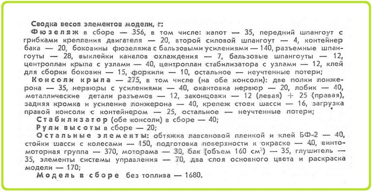
By Criekey ! :
The famous design of the cord model by Valentin Salenek "Championship Novelty 85"
Everything about this cordless model is unusual. Increased dimensions, weight, specific load and engine cubic capacity, unconventional proportions of the empennage arms and geometric dimensions of the wing, an organic combination of plane contours and original fuselage outlines - all indicate the designer's desire to find a single optimal solution in the most complex and at the same time popular aerobatic class.
---------------------
New findings in aerodynamics and the design of individual units have given the model as a whole unique aerobatic properties. A successful compromise of stability and high maneuverability, low sensitivity to wind, unpretentiousness of the model in handling all figures - these are the characteristics of the cordova of the famous Moscow athlete Valentin Salenek, who attracted everyone's attention at the 1985 USSR Championship. They allow us to say: this technique can become the "progenitor" of the future generation of acrobatic cord models.
The new aerobatic model has detachable wing and stabilizer planes, keel, landing gear. The connector is also introduced into the fuselage at the flap attachment point. As a result, the disassembled line aerobatic model with all the launch equipment can be placed in a box measuring 250X400 X800 mm.
----------------------------
The fuselage connectors behind the wing and along the keel provide convenient access to all adjustable control units and allow you to quickly match the flap and elevator hog arms to match the athlete's handling requirements.
A large number of docking points does not diminish the reliability of the model. The experience gained in the process of working with aerobatic models of this type and the rather long-term operation of the last option showed that the careful execution of the connector parts completely insures against surprises even when flying in the most unfavorable weather conditions.
In terms of weight, the fully-disassembled model is easily brought into compliance with any, the most stringent standards (of course, with the correct execution of the nodes). The advantages of transporting and debugging such equipment are undeniable.
--------------------------------------
The technology for making aerobatics basically corresponds to that described in " MK " No. 6 and 7 for 1983. (Pilotage of the eighties) The fuselage of the model is a carrying sandwich monocoque from an outer power fiberglass "crust", a layer of foam filler and an inner thin fiberglass "skin".
===============================================
The front sub-engine frame (re-adhesive of six layers of plywood 1 mm thick), after cutting the relief windows, is sheathed on both sides with the same plywood. Frames are installed at the ends of the detachable parts of the fuselage - two sheets of plywood 1 mm thick (glued and lightened, on the outside the third layer-skin is glued).
To increase the reliability of fastening the frames with the supporting gluing of the fuselage in the foam breaks, balsa strips-inserts are placed on the molded power "crusts".
The inner layer is formed by glass cloth 0.02 mm thick. During assembly, the monocoque structure is cut under the frames to the outer skin. Balsa frames are pre-mounted along the runners (the joint line is vertical) in the right and left parts of the fuselage gluing.
Before final assemblyall frames are adjusted to their places, balsa half frames are glued in on the PVA emulsion, the frames of the fuselage connector are pulled together using standard model units with a gasket along the junction of a balsa sheet 1 mm thick (this size must be maintained over the entire area of the joint, otherwise the tail section may later go to the side ). Then the finished wing and the stabilizer are cut into the gluing, the relative position of these parts is verified and the "filling" of the aerobatic is roughly mounted. Having carefully thought out the sequence of assembly operations, control of the symmetry of the model, the functioning of mechanics and its debugging, they fasten the fuselage to the wing and stabilizer with epoxy glue. After the resin has hardened, the screws tightening the fuselage parts are unscrewed, and the gluing is carefully cut along the balsa insert. The joint planes are carefully adjusted to each other.
The box-section keel ribs are assembled from 1 mm thick balsa plates and mounted on the fuselage. Their outer surfaces are covered with thin mica paper on parquet varnish, putty with a composition of talc and parquet varnish (a layer of minimum thickness is applied, covering only microracosins on the balsa pores), the same composition is applied to the non-glued areas of the fuselage, the entire surface is cleaned.
A few words about the features of the split wing manufacturing . As in the fuselage assembly, the butt ribs (balsa, sheathed with 1 mm plywood on the docking side) are pulled together with a little effort by the standard wing connector assemblies so as not to crush the balsa two-millimeter false rib-gasket, after which they are mounted in the wing frame. Before that, it is necessary to put their mounting imitators made of wood in the places where the studs are installed. Then you can start covering the wing, its forehead and central part with balsa veneer. The finished frame is carefully sawn along the parting lines, the ends are sanded and additionally sheathed with millimeter plywood. Retaining pins are installed, the wing is reassembled and smoked.
Sheathing of bearing planes - lavsan film . The consoles are covered 2-3 times with liquid glue BF-2 with sanding each layer after it dries, finally another layer is applied, without stripping, and after drying, a film is applied with the painted side out. This is how the entire surface of the consoles is sheathed, the endings are finished with mica paper on parquet varnish, and subsequently only places not covered with lavsan film and the places where the paper transitions to the film are putty.
The stabilizer and rudders with flaps are inlaid, sheathed also with lavsan film. The control system is designed to allow easy replacement of the bushings during operation. All parameters of the control system are adjustable over a wide range.
======================================
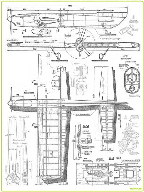
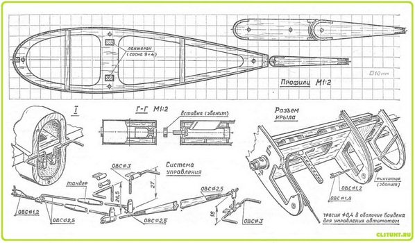
The model is equipped with an automatic engine shutdown,triggered by the tension of the cords in 12-13 kg, this value is easily adjusted due to the design of the machine. Its mechanism is mounted between the flanges of the wing spar, the executive part - a rod with a needle and a pawl - on the rear wall of the engine. The dog is supplied with a flexible rod in a Bowden sheath, coming from the automatic stop. The control rocker is made of D16T sheet 3 mm thick; on the machine it is hung with an axle made of OBC 0 2.5 mm wire and a BRB-2 bronze bearing sleeve. Two guides are mounted on the rod, the upper one simultaneously serves as a cable drive. The groove for the cable termination is oblong, therefore the actuator of the executive mechanics remains stationary throughout the entire range of the flight tension of the cord. The actuation forces are adjusted with a screw with a slot for a screwdriver, which is fixed after debugging with a wire cotter. The power spring of the machine is wound from wire OBC 0 1.5 mm. The exit of the cord from the wing allows adjustment of the distance between them and the joint position of the cord relative to the center of gravity of the model. The divergence of the suspension points on the control handle is 100 mm.
The finishing of the model is extremely simplified. Areas with lavsan coating practically do not need puttying and creating a subcoat under the paint. The film perfectly closes even large balsa pores. And in order to eliminate minor imperfections in the surface finish, the model is painted twice with polyurethane enamels. After complete drying, the first layer is lightly sanded, if necessary, a local putty is applied, then the final layer of paint is applied. The centering of a complete model should be on the wing spar. By adjusting the flight characteristics to the individual characteristics of piloting, the center of gravity can be shifted up to 10 mm in both directions.
The model is designed for a home-made glowing engine with a working volume of 9.3 cm3. Piston diameter 23.2 mm, stroke 22 mm, suction distribution - by a cylindrical valve in the rear wall of the crankcase. The crankshaft rotates in 10X22 and 7X17 ball bearings. Gas distribution phases: exhaust - 136 °, bypass - 120 °, intake - 180 °, start of intake - 40 ° after BDC. Diameter of the carburetor foot is 5.6 mm (ring type jet).
Engineequipped with an effective home-made muffler, which is mounted on a removable engine mount and mates with the exhaust pipe according to the principle known to speeding people. The motor frame is milled from alloy D16T; it is fixed on the sub-frame frame with four M4 screws through rubber shock absorbers. The tank - a round plastic bottle with a diameter of 42 mm and a length of 120 mm - is located along the axis of the engine crankshaft. The best results were obtained with a three-bladed propeller made of basswood. In conclusion, I would like to note that the highest requirements are imposed on the moto installation. Figuratively speaking, it is not the model that is flying, but the engine, which largely determines the behavior of the aerobatic in all flight modes. Without a powerful, reliable and responsive motor, the best technology can be non-volatile. In the vast majority of cases, modelers do not take this into account, probably the most important factor, they build aerobatic line models according to the drawings of popular aerobatic models and ... fail. Then they refer to inaccuracies in the drawings, publication errors and any other reasons, forgetting the main thing - the famous model was created for a specific power plant. And its replacement entails the need to design the entire aerobatic model from scratch.
Valentin Salenek
From the magazine Modelist Constructor
Read the beginning of Valentin Salenek's article at the link: Cordless aerobatic model "Aerobatics of the Eighties"
=======================================================================
--------------------------------------------------------------------------------------------------------------------------------
=======================================================================
Liberated from Evgeny Khromov site .


 Topic: Identify this Russian Plane (Read 3715 times)