From the top drawing it appears the highest pressure is on the nose ( Red ) the blue bit being percentges.
Here the intake to oil tank and crankcase , he was concerned to keep bearing temperture manadgeable , is about the spinner .
tho flow largly depends on pressure diffrential . Assumedly a spinner half the size the pressure there would be somewhat greater .
Matching Diameter , flow past may well create a relative vacume - lower presure at periphery than INSIDE the cowling .
Whereas a larger spinner diameter than cowl diameter , with a longitudeinal gap . as in between backplate and ' spinner ring ,
would create the ' flow through area .' .
Itd be adviseable to have the gap say three times the step , If aiming for extraction at the rear spinner face .
Still , the intakeelsewhere should provide a pressure in the motor compartment well above that flowing past the periphery .
Unless youre sure of produceing a significant suction at the outlet ( periphery again ) .
Id like to see a smoke wand to provide evidence that a smaller spinner than fuse would actually evacuate air there .
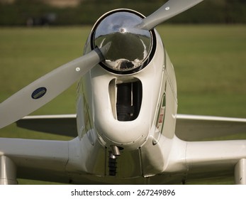
Id assume it works ( if as per the picture / photo ) as pretty much a boundary layer intake , enhancing flow past the fuselage . perhaps .
With the intake as built on the model ( the normalish looking one , a floor under the motor adhered forward & sides , rear edge aft of motor ,
with a wall a inch or so aft of that edge , would have the cooling air going forward through the motor , if semi directed there ,
with a floor over the motor sealed aft & sides , gap forward .Presumably from there back aft agin to some outlet .
--------------------------------------------------------------------------------------------------------------------------------------
Id consider a similar flow for a I C engine , from a P 51 dog house ( F S Radiator chamber ) so the air'd go forward and round and back , then out .
A rectangular box up , aft wall at the rad. there . A compartment even . with a rectangular shaft 1/4 the size going forward . Maybe at the top .
The shaft coming back aft splittingarond the ides , opening at the rad. there , to the rear chamber .
Sorta uses the full size P 51 pricaples . Small take off in airflow to big chamber , to reduce speed & losses.
Rear chamber outlet in low pressure zone with high flow past speed , the air there falls out to match airspeed .
As you need no fuel proffing , light 20 thou cardboard'd do . at least for a test set up .
But we mayve wandered a bit off from the original quetion there .

Will scribble a illustration if you require . No fuel tank in the way , anyway . And ' top ' is irrelevant with as much time either way up , give or take .
Its the PRESSURE DIFFRENTIAL that does the work - for flow rates . As long as changes of direction arnt constrictive .

Maybe it'd be a lot easyer built as a pusher .


 Topic: Cooling Fan using rear/through the bulkhead rear mount (Read 5333 times)